
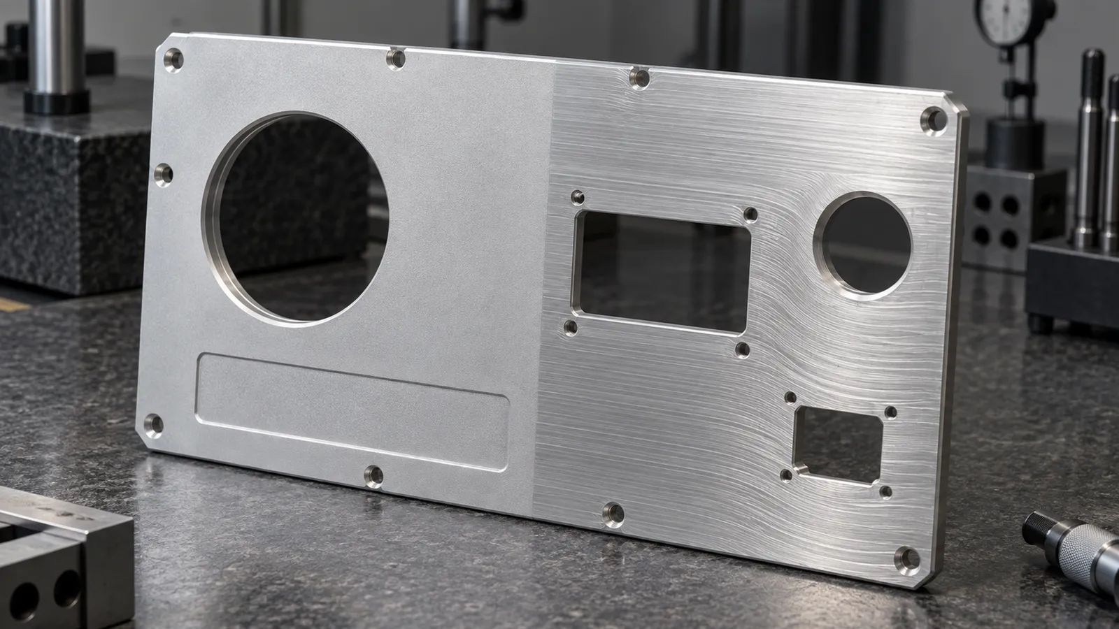
Direct answer: A robot face panel is a cosmetic part with a mechanical job, and clear anodize is the finish that refuses to hide either. Because Type II Class 1 is undyed, everything under the film still shows — tool marks, witness lines between passes, grain direction, and any handling damage. So a face panel drawing needs four things a bracket drawing does not: a pre-anodize surface texture called out as a finish, not left to the shop; a flatness and thickness control that survives a thin panel being clamped; a stated location for rack marks; and a masking plan for grounding pads and sealing faces. Get those on the print and the panel is quotable. Leave them off and the first article will be rejected for appearance, not for dimensions.
Specification summary
| Parameter | Typical for a clear anodized face panel | Reference |
|---|---|---|
| Alloy | 6061-T6 / T651 plate | ASTM B209 |
| Finish | Type II Class 1 (undyed), sealed | MIL-A-8625 |
| Film thickness | 5–15 µm for cosmetic panels | MIL-A-8625 Type II |
| Dimensional growth | About half the film thickness per surface | — |
| Pre-anodize texture | Bead blast to a stated grit, or a stated Ra | ISO 4287 |
| Panel flatness | 0.1–0.3 mm over the panel, free state, typical | ISO 1101 |
| Cosmetic zone | Defined on the drawing as A / B / C surfaces | — |
| Rack mark location | Named on the drawing, in a B or C zone | — |
| Marking | Laser, contrast stated as a requirement | — |
These are starting points for a drawing review rather than universal values. Panel size, thickness and the customer’s own cosmetic standard move all of them.
Why a face panel is a different part from a bracket
A bracket is accepted on measurement. A panel is accepted on measurement and on how it looks from a meter away, which is a specification almost no drawing states.
The panel is the part of the machine that sits at eye level in a customer’s cell. It carries the connector cut-outs, the legends, sometimes a display window, and it is the surface a maintenance technician touches every week. That gives it three requirement sets at once:
- Mechanical — it seals, it mounts flat, and its cut-outs have to line up with hardware behind it.
- Cosmetic — color, texture and freedom from defects, judged by eye.
- Electrical — grounding paths and EMI contact areas, which anodize will insulate if nobody masks them.
Most face panel disputes come from the second set, because it is the only one that usually arrives on the drawing as a single word: “anodized”.
Why clear anodize hides nothing
Clear anodize is not a coating color. Type II Class 1 has no dye in it, so the finished appearance is the aluminum underneath, seen through a transparent oxide film.
That has a specific consequence for machining. A dyed black panel can absorb a surprising amount of surface variation, because the dye fills the visual range. A clear panel cannot. What shows through:
- Cutter witness lines where two toolpaths meet, even when the step is well inside the dimensional tolerance.
- Direction of the finishing pass. A face milled in one direction and a face milled across it will read as two different shades at the same angle of light.
- Grain and rolling direction in the plate.
- Alloy. 6061 gives the neutral silver most people mean by “clear”. 7075 tends to a yellowish cast, and 2024’s copper makes it worse still. Mixing alloys across a panel set will not color-match.
- Handling marks from after the last machining operation, which the film then seals in permanently.
The practical rule: on a clear anodized panel, surface preparation is the appearance. Anodizing only makes it durable.
Calling out the pre-anodize texture
The single most useful line you can add to a face panel drawing is what the surface should look like before it goes in the tank.
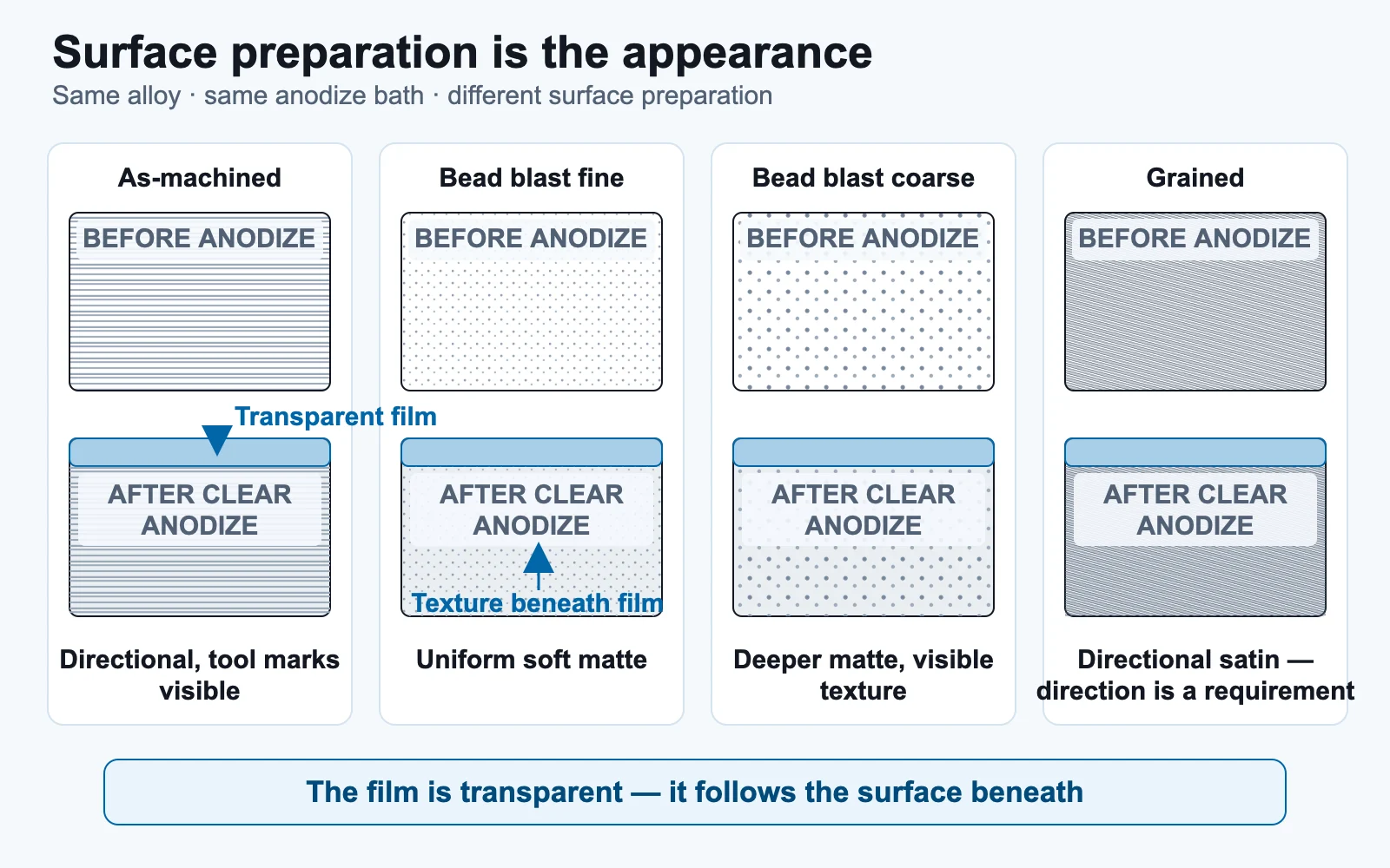
Three common routes, and what each buys:
| Pre-anodize texture | Result after clear anodize | Where it fits |
|---|---|---|
| As-machined | Tool marks visible and directional; cheapest | Internal panels, or a deliberate machined look |
| Bead blast to a stated grit | Uniform matte; hides toolpath differences | Most exterior face panels |
| Grained / brushed to a stated direction | Directional satin; the direction becomes a requirement | Consumer-facing equipment |
If the drawing says only “clear anodize”, the shop will usually blast — because it is the safest way to get a uniform panel — and you will get whatever grit is loaded that week. Stating the grit, or an Ra range, is what makes two batches match. See surface roughness options for how to write the roughness call, and the bead blasted finish page for the texture itself.
Flatness on a thin panel
A face panel is usually the thinnest large part in the assembly, which makes it the one most likely to move — while machining, while clamped, and after unclamping.
The problems are mechanical, not cosmetic, but they land on a cosmetic part:
- Clamping distortion. Hold a thin panel down hard, face the surface flat, release it, and the panel returns to the shape it wanted. The face is then flat only while clamped.
- One-sided pocketing. Cut-outs and counterbores from one face unbalance the residual stress, the same mechanism described in the 2024 distortion guide — and it applies to 6061 plate too, just less violently.
- Sealing faces. If the panel carries a gasket, its flatness is a functional requirement and belongs in a feature control frame, not in a general note.
What to put on the drawing:
- State flatness in the free state, and say so explicitly —
FLATNESS 0.2 FREE STATEremoves the ambiguity that “flat” alone creates on a thin part. - Give the datum scheme the assembly uses, not the largest face. The datum scheme guide covers how to choose it.
- Say whether flatness applies before or after anodize. A 10 µm film does not warp a panel, but the pre-clean and the tank cycle involve heat, and a marginal panel can move.
Rack marks: decide where they go, because they will exist
Anodizing needs electrical contact with the part. Wherever the rack touches, there is no coating — a small bare or discolored spot. This is not a defect; it is how the process works. The defect is finding it in the middle of the visible face.
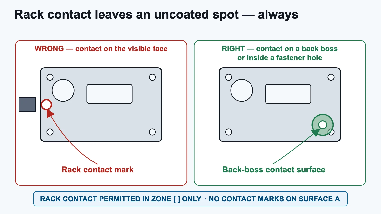
Face panels are the part where this matters most, and it is almost never on the drawing. Handle it in one of three ways:
| Approach | How it works | Trade-off |
|---|---|---|
| Name the location | Drawing marks an allowed contact zone, usually a back-face boss, an edge, or inside a cut-out | Best result; costs nothing if decided early |
| Use a mounting hole | Rack contacts inside a through hole that a fastener later covers | Free, but limits rack design on large panels |
| Leave it to the finisher | Contact goes wherever the rack design is convenient | Will eventually appear somewhere you did not want |
The drawing line is simple: RACK CONTACT PERMITTED IN ZONE [ ] ONLY. NO CONTACT MARKS ON SURFACE A.
Defining cosmetic zones instead of writing “cosmetic”
“Cosmetic finish” is not inspectable. Zoning is: split the panel into surfaces with different acceptance levels, and say what is allowed on each.
A common three-level scheme:
- A surfaces — seen in normal use, at normal viewing distance. Tightest limits, no rack marks, no handling marks.
- B surfaces — seen occasionally, or at an angle. Minor variation allowed; small marks permitted within a stated size.
- C surfaces — hidden in the assembly. Function only; rack contact allowed here.
Then give acceptance the two conditions that make it repeatable: viewing distance and lighting. A panel inspected at 300 mm under a bright inspection lamp and the same panel at arm’s length under office lighting are two different parts. Naming both — and, on a recurring program, agreeing a limit sample — is what stops the argument.
For color consistency across batches, the honest expectation is on the clear anodize page: undyed film on one alloy from one plate lot is consistent, and across alloys or lots it drifts. If panels must match each other, say they are a matched set and they will be processed together.
Masking: grounding, sealing, and fits
Anodize is an electrical insulator. Every ground path, EMI contact strip and bonding pad on a panel has to be masked, or the panel will pass cosmetic inspection and fail continuity.
What normally gets masked on a face panel:
- Grounding and bonding pads, including the area under a star washer.
- EMI gasket contact strips around the perimeter or a display opening.
- Press-fit and slip-fit features where the film’s growth would close the fit.
- Threaded holes where the class of fit matters, though a Type II film is thin enough that many panels accept threads as-coated — state which you want.
Where a masked area still needs corrosion protection, chem film is the usual partner finish: conductive, and compatible with anodize on the same part. Call it out as a separate finish line, not as a note inside the anodize call.
Laser marking legends on clear anodize
Laser marking a clear anodized panel produces a dark mark on a light field — the inverse of the bright-on-black most people picture — and the contrast depends on the film and the parameters, so it has to be a stated requirement rather than an assumption.
Points worth putting on the drawing:
- Mark before or after anodize. Marking after anodize on a clear film is the common route for legends. Marking before means the mark is under the film, which is more durable but lower contrast.
- Contrast as a requirement, not just artwork. “Legible at 500 mm under office lighting” is a testable line.
- Position relative to the cosmetic zones — a legend is an A-surface feature and should be dimensioned from the same datums as the cut-outs.
- Artwork format. Vector artwork, with the text as outlines, avoids the font substitution that turns a symbol into a different symbol.
See the laser marking page for the method, and the clear versus black comparison if the panel’s finish is still open — silver-on-black gives the highest legend contrast aluminum offers, and it is the reason many instrument panels are black.
What goes on the face panel drawing
- Alloy, temper, form and spec — one alloy across a matched panel set
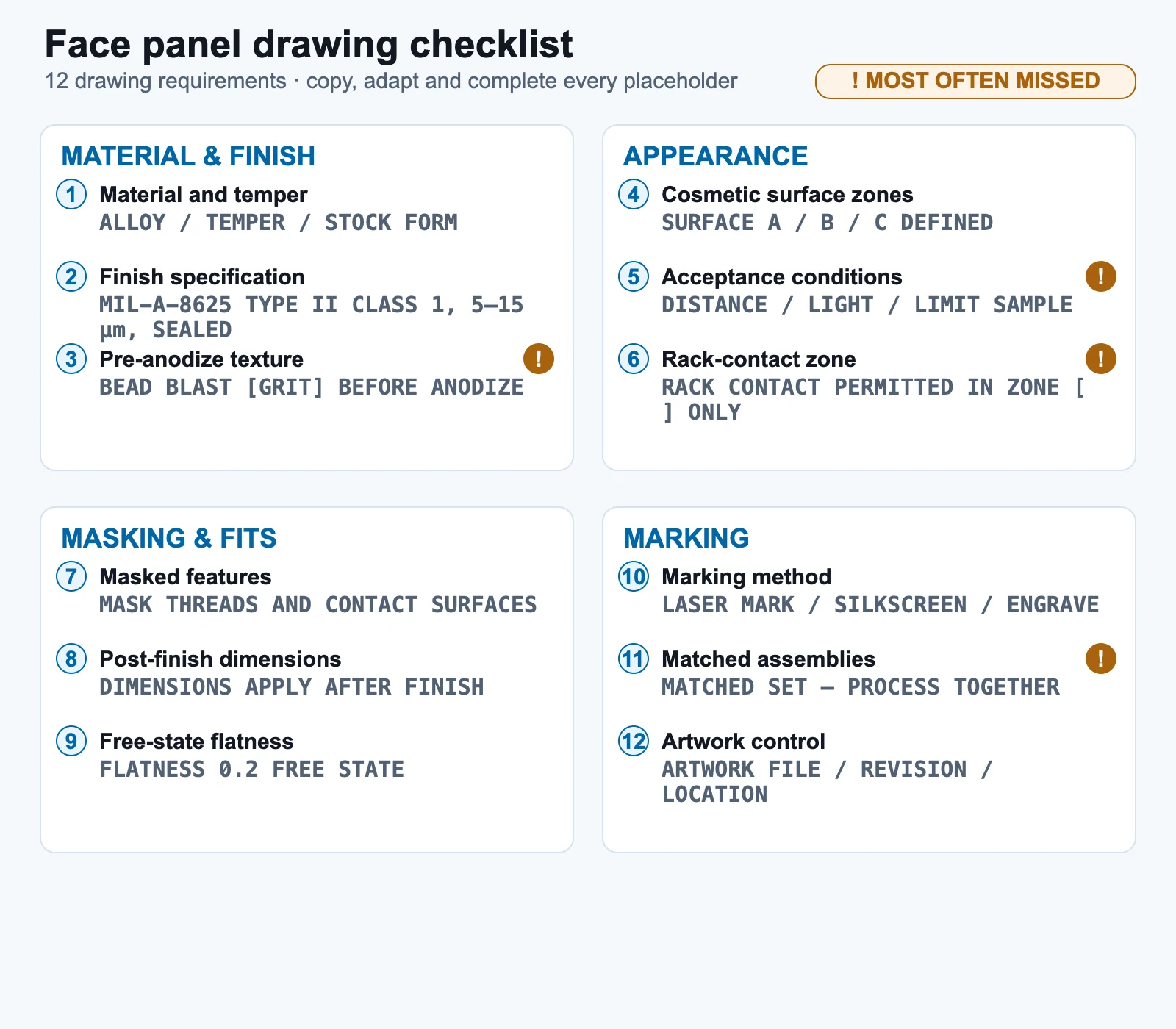
Items 3, 5, 6 and 11 are the ones we most often have to ask for. If you are assembling the wider package, how to prepare drawings for CNC quotes covers the rest.
Common mistakes
- “Clear anodize” with no pre-anodize texture. The texture is the appearance; the anodize is only the film over it.
- Cosmetic requirements with no viewing conditions. Unrepeatable, and it always surfaces at first article.
- No rack contact zone. The marks exist either way; only their location is negotiable.
- Grounding pads unmasked. The panel looks perfect and fails continuity.
- Mixed alloys in a matched set. 6061 and 7075 will not color-match under a clear film.
- Flatness specified but not in the free state, on a panel thin enough to be held flat by the fixture.
- Marking artwork supplied as a font name rather than outlines.
- Cut-outs dimensioned from the panel edge instead of the assembly datums, so the connectors sit visibly off-center.
FAQ
What finish should a robot face panel have?
Type II Class 1 clear anodize over a stated pre-anodize texture — usually bead blast to a named grit — is the common choice for a silver panel. The finish call alone is not enough: state the texture, the film thickness range, the cosmetic zones and the rack contact location, because on an undyed film everything under the coating remains visible.
Why do two clear anodized panels from the same drawing look different?
Usually because something below the film differed: a different plate lot or alloy, a different blast grit, or a finishing pass run in a different direction. Undyed anodize adds no color of its own, so it cannot hide those differences. Specify the alloy, the pre-anodize texture and, for panels that must match, process them as a matched set.
Where do rack marks go on an anodized panel?
Wherever the drawing allows them — and if the drawing is silent, wherever the finisher’s rack design is convenient. Anodizing requires electrical contact, so an uncoated contact point always exists. Name a permitted contact zone on a back face, an edge, or inside a fastener hole, and state that no contact marks are allowed on the visible surface.
Does clear anodize change panel dimensions?
Yes, by about half the film thickness on each surface, so a 10 µm film adds roughly 5 µm per face and closes a hole by about 10 µm on diameter. On a face panel this matters for press fits, dowel holes and tight cut-outs rather than for the flat faces. State whether toleranced dimensions apply before or after coating.
How do you specify a cosmetic finish so it can actually be inspected?
Replace the word “cosmetic” with three things: zoned surfaces (A, B, C) with different limits, the viewing distance and lighting under which the panel is judged, and — for recurring work — an agreed limit sample. Those turn an opinion into an inspection.
Can a clear anodized panel be laser marked?
Yes. Marking after anodizing produces a dark mark on the light film, which is the usual route for legends on clear panels. State the contrast you need as a requirement rather than assuming it, supply vector artwork with text converted to outlines, and dimension the mark from the same datums as the cut-outs.
Should a face panel be 6061 or 7075?
6061 for almost every face panel. It gives the neutral silver that “clear anodize” implies, and panels are rarely strength-limited. 7075 anodizes to a yellower cast and costs more, so it belongs on the structural parts behind the panel — see 6061 vs 7075.
Conclusion
The mechanical half of a face panel is ordinary work. The half that causes rejections is the half the drawing usually leaves as one word. Name the pre-anodize texture, zone the surfaces, give the acceptance its viewing conditions, put the rack marks somewhere you chose, and list every area that has to stay conductive.
Send the panel drawing and the artwork together and we will return a finish, masking and cosmetic-zone review before the quote fixes assumptions nobody stated.