
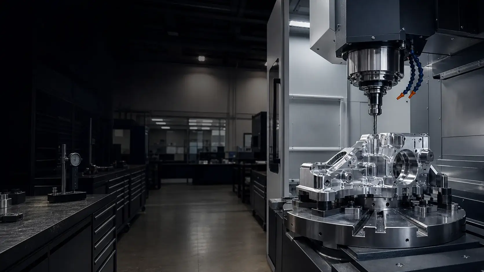
Pocketed structural links machined from 7075 plate, lightweighted along the load path with located bearing bores at each joint.
Robotics & end-of-arm hardware
Aluminum CNC Machining for Robotics
Every gram on a robot arm is payload you don't get back. We machine aluminum robotic components where mass, stiffness, and bore location are the design currency — arm links, end effectors, servo housings, and the brackets between them.
Robotics teams iterate fast; our engineering review keeps up, returning DFM feedback on your CAD within one business day from prototype through recurring production.
- ISO 9001:2015
- Prototype to production
- Engineering review within one business day
- Material certificates available
- FAI reports available
Typical components
Robotic components we machine from aluminum
From the base casting interface to the tool flange, most of a modern robot's machined mass is aluminum — these are the parts that cross our machines most often.
EOAT plates, gripper fingers, and quick-change adapters where every gram at the wrist subtracts directly from payload.
Motor mounts and harmonic-drive interfaces with pilot bores positioned to the bolt circle so shafts align without shimming.
Stable mounts for vision, lidar, and force sensors that hold calibration through thermal cycles and vibration.
Rail mounting plates machined flat and parallel so linear axes stay square over full travel.
Turned pulley shafts, spacer stacks, and adapter sleeves with bearing seats and gauged threads.
Recommended aluminum grades
Alloy selection for robotic hardware
Robotics splits cleanly between structure and everything else: 7075 where the FEA is tight, 6061 everywhere it isn't.
| Alloy | Why this industry specifies it | Typical parts |
|---|---|---|
| 6061-T6 | The default for brackets, housings, and EOAT details — stiff enough for most joints at half the cost of 7075, and it anodizes uniformly for visible cell hardware. | Brackets, gripper bodies, sensor mounts, guards |
| 7075-T6 | Near-steel yield strength keeps arm links and joint structures inside their mass budget. Specify T651 plate for heavily pocketed links. | Arm links, joint housings, loaded wrist components |
| 2024-T351 | Worth considering on high-cycle joints where fatigue governs — robots that run 24/7 accumulate load cycles fast. | Cyclically loaded pins, clevises, and linkage parts |
| MIC-6 cast plate | For the cell around the robot: base plates and calibration platforms that must stay flat as references. | Robot base plates, cell platforms, calibration fixtures |
| 5052-H32 | Covers and guards on washdown and food-handling robots, where corrosion resistance outranks strength. | Covers, shields, and washdown-cell hardware |
Machining challenges
What makes robotic parts demanding to machine
Robot hardware concentrates three difficulties at once: aggressive lightweighting, located bores that define kinematics, and batch-to-batch repeatability across iterations.
Pocketing 60% of a 7075 link's volume releases stress and moves geometry. We sequence roughing, intermediate measurement, and finishing so the bearing bores end up where the kinematic model expects them — not where the plate relaxed to.
Joint-to-joint bore distances go straight into DH parameters. We machine bore pairs in single setups and inspect center distances, not just diameters, holding ±0.02 mm where the drawing demands it.
Robotic housings run 1–1.5 mm walls to save mass. The machining answer is light finishing passes and support-aware toolpaths; the design answer is uniform wall thickness — we flag both at review.
Servo interfaces, cable routing, and mounting faces land on five sides of a housing. 5-axis machining keeps their relationships inside one setup instead of stacking re-fixturing error.
Robot joints get re-torqued at every maintenance interval. We recommend helical inserts on all serviced threads — aluminum threads are the wear item, not the fastener.
Rev C of an arm link must locate exactly like Rev B where the interfaces didn't change. We hold datum schemes stable across revisions so your assembly and calibration process doesn't reset each iteration.
Surface finishing
Finishes for robotic hardware
Robot parts are handled, cabled against, and photographed in customer demos — finish selection covers wear, grounding, and appearance in one decision.
The robotics default: kills reflections that confuse vision systems, hides handling wear, and reads professional in customer-facing cells.
For internal structure and heat-dissipating housings where the machined finish should stay visible and corrosion-protected.
On gripper contact zones, cam surfaces, and quick-change interfaces that see thousands of engagement cycles.
For grounding paths and EMI bonding on servo housings — anodize is an insulator, and a floating housing is a noise problem.
Uniform matte for exposed arm surfaces; specify the grit so replacement parts match the original build.
Joint IDs, axis labels, and torque specs marked permanently where technicians actually look during maintenance.
Full finish specifications live in the aluminum surface finishes hub — including clear anodized, black anodized, hardcoat anodized, chem film, and laser marking guides.
Inspection & quality
Inspection matched to kinematic requirements
Robotic hardware quality is about the dimensions that enter the kinematic chain. We inspect what the robot's accuracy depends on, and document it so your commissioning team isn't guessing.
- CMM verification of bore positions
Joint bore center distances and perpendicularity measured and reported — the numbers your calibration offsets come from. - First article inspection
Full FAI on new part numbers and on revisions that touch interface geometry. - Bearing seat and fit checks
H7 bores and g6 seats gauge-verified, with post-anodize verification where coatings land on fits. - Thread inspection
Gauged threads plus insert installation verification on serviced joints. - Material certificates
Alloy and temper traceability per heat lot — standard on 7075 structural links. - Batch dimensional reports
Recurring production ships with dimensional reports on agreed critical features, so drift is caught at our machines, not your assembly line.
Project gallery
Robotic aluminum machining examples
Representative robotics work: lightweighted structures, located interfaces, and anodized assemblies.
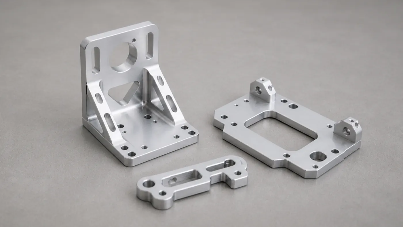
Joint brackets and mounting plates
7075 and 6061 robot brackets with located bearing bores and dowel patterns.
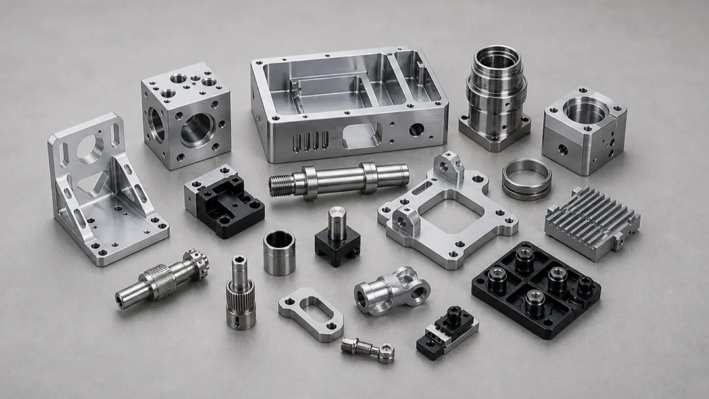
EOAT and drivetrain hardware
Gripper details, spacers, and servo interface parts machined as matched sets.
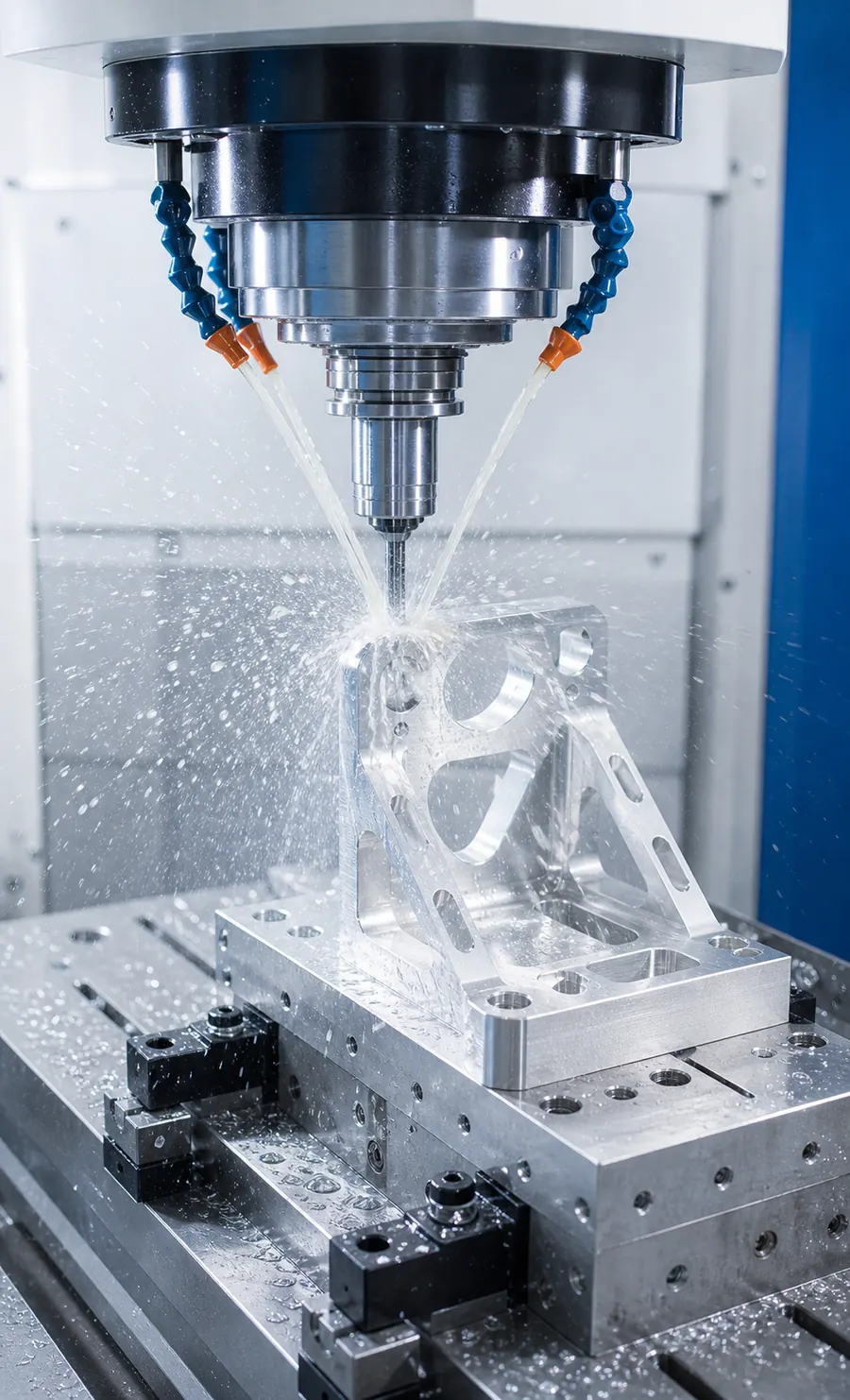
Arm link machining
Pocketed structural links milled with stress-aware roughing and finishing sequences.
Related guides
Guides robotics teams use next
The product and industry guides that overlap most with robotic hardware programs.
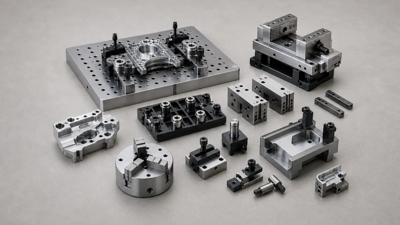
Aluminum CNC machining for automation equipment
The cell around the robot: frames, fixture plates, conveyor hardware, and pneumatic manifolds.
Custom aluminum CNC brackets & mounts
The bracket engineering guide: dowel location, hole patterns, and 7075 selection.
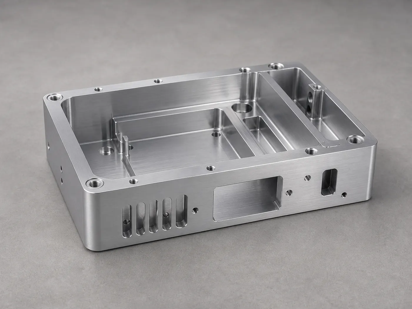
Aluminum CNC machining for electronics housings
Controller enclosures, sensor housings, and EMI-managed boxes for robot electronics.
Case studies
Case studies from this industry
Representative aluminum CNC projects for this sector — with specifications, engineering challenges, and inspection notes.
Robotics 7075 Robotic Arm Bracket — Lightweight Structural Link
A 7075-T6 structural arm bracket with lightweighting pockets, precise bearing bores, and hardcoat anodize, machined for stiffness-to-weight in a robotic joint.
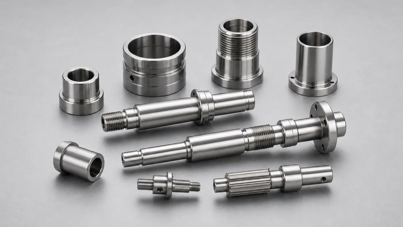
Precision Turned Parts Precision Turned Aluminum Shaft — 7075 Mill-Turn Component
A 7075-T6 turned shaft with bearing seats, gauged threads, and cross-drilled mill-turn features, held to tight concentricity for a rotating motion assembly.
Automation Equipment Automation Gripper Baseplate — Dowelled 6061 Tooling Plate
A 6061-T6 gripper baseplate with an H7 dowel grid, sensor pockets, and hardcoat anodize, built as a repeatable, wear-resistant mounting base for high-cycle end-of-arm tooling.
Browse the full engineering portfolio in the aluminum CNC machining case studies hub.
Quote your robotic aluminum parts
Upload arm links, EOAT, or housing CAD with alloy, finish, and critical bore callouts. An engineer reviews lightweighting risk, bore datums, and thread service life — feedback and quote within one business day, prototype through production.
- Prototype to production
- Engineering review within one business day
- Material certificates available
- ISO 9001 quality management