
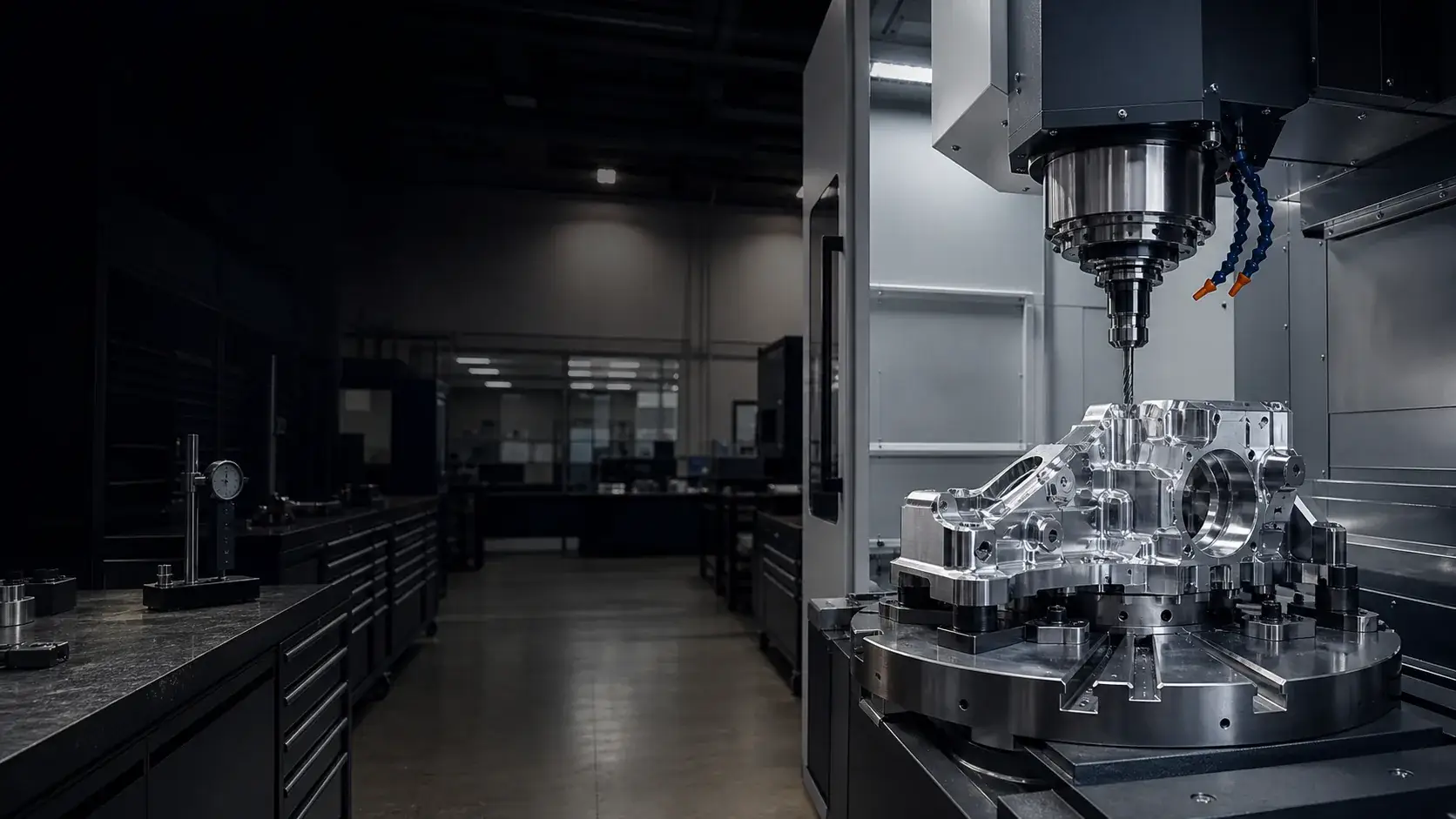
Bearing seats, shoulders, and threads all have to run true to the shaft axis. Turning them in as few setups as possible — with mill-turn for the off-axis features — keeps runout down.
Case study · Precision turned parts
Precision Turned Aluminum Shaft — 7075 Mill-Turn Component
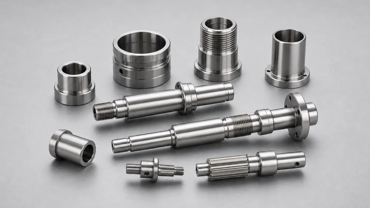
A 7075-T6 turned shaft with bearing seats, gauged threads, and cross-drilled mill-turn features, held to tight concentricity for a rotating motion assembly.
- 7075-T6
- Concentricity
- Mill-turn
Project overview
Project overview
This project is a 7075-T6 turned shaft with mill-turn features — bearing seats, shoulders, gauged threads, retaining grooves, and off-axis cross-holes on a single rotating component for a motion assembly. It is a turning-led part, but the flats and cross-holes make it a mill-turn job rather than pure lathe work.
Everything about the part comes down to concentricity. The bearing seats, shoulders, and threads all have to run true to the shaft axis, because runout at a bearing seat turns into vibration and wear everywhere downstream. Machining the on-axis and off-axis features in as few setups as possible — using mill-turn for the flats and cross-holes — keeps runout down, and finish turning passes hold the bearing seats to Ra 0.8 µm and the specified fit class. Because a long, slender aluminum shaft deflects under cutting load, support and light finishing passes keep the diameters consistent along its length.
Fit surfaces are typically left as-machined so no coating alters their size, with optional clear anodize on non-fit surfaces. Length, diameters, runout values, and volumes are placeholders — the concentricity strategy and mill-turn approach are representative of the turned parts we machine.
Technical specification
Part specification
Key manufacturing parameters for this project. Values marked as placeholders stand in for confidential production data.
| Parameter | Specification |
|---|---|
| Overall length | Placeholder — e.g. 140 mm long, Ø25 mm max |
| Bearing-seat concentricity | TIR held tight across seats — placeholder for value |
| Diameter tolerance | Bearing seats to h6 / specified fit class |
| Threads | Gauged threads per drawing |
| Grooves / features | Retaining grooves, flats, and cross-holes (mill-turn) |
| Surface finish | Ra 0.8 µm on bearing seats |
Engineering challenges
What made this part difficult
The manufacturability risks we planned around before cutting metal.
Bearings need a smooth, correctly sized seat. Finish turning passes and controlled tooling held the seats to Ra 0.8 µm and the specified fit class.
Long, thin aluminum shafts deflect under cutting load. Support and light finishing passes kept diameters consistent along the length.
Manufacturing process
How the part was made
The routing from raw stock to finished, inspected components.
- Step 1: Engineering review
Confirmed fit classes, concentricity callouts, and mill-turn features before quoting. - Step 2: CNC turning
Shaft turned from 7075-T6 bar with roughing and finishing passes for diameters and shoulders. - Step 3: Threading and grooving
Threads cut and gauged; retaining grooves turned to size. - Step 4: Mill-turn features
Flats, cross-holes, and off-axis features machined in the same platform to preserve concentricity. - Step 5: Deburr and clean
Edge-break, thread cleaning, and inspection prep. - Step 6: Optional anodize and inspection
Clear anodize if specified, then concentricity and thread verification.
Inspection methods
How quality was verified
Dimensional and process controls used to sign off the part. See our full aluminum part inspection process.
Bearing seats and shoulders checked for TIR against the shaft axis. Placeholder for the specified runout value.
Threads verified with go/no-go gauges.
Full FAI on the first shaft with a report available; placeholder for AQL.
Surface finishing
Finishing and post-processing
Finishing decided alongside the machining plan. Compare options in the aluminum surface finishes hub.
Bearing seats and fit surfaces typically left as-machined so dimensions are not altered by coating.
Clear anodize available for corrosion protection on non-fit surfaces, with fit diameters masked.
Typical application
Where this shaft is used
Turned shafts carry rotating motion in automation and robotics assemblies — spinning in bearings, carrying pulleys or gears, and locating parts along their length with shoulders and grooves.
Concentricity is everything: runout at a bearing seat becomes vibration and wear downstream, so the value of the part is in how true it runs, not just its diameters.
- Manufacturability review
Every project starts with an engineering review of tolerances, wall thickness, and finish before we quote. - Prototype to production
The same routing scales from a first article to recurring production batches. - Documentation
Material certificates and first article inspection reports are available on request.
Explore the engineering
Related capabilities, materials, and pages
This project connects to our wider aluminum machining program. Start with our engineering capabilities, then dive into the specific products, materials, industries, and finishes involved.
Case studies
More aluminum CNC machining case studies
Projects with comparable materials, tolerances, or finishing requirements.
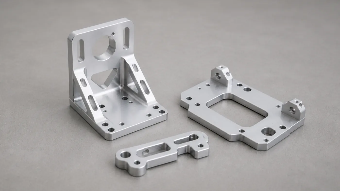
Robotics 7075 Robotic Arm Bracket — Lightweight Structural Link
A 7075-T6 structural arm bracket with lightweighting pockets, precise bearing bores, and hardcoat anodize, machined for stiffness-to-weight in a robotic joint.
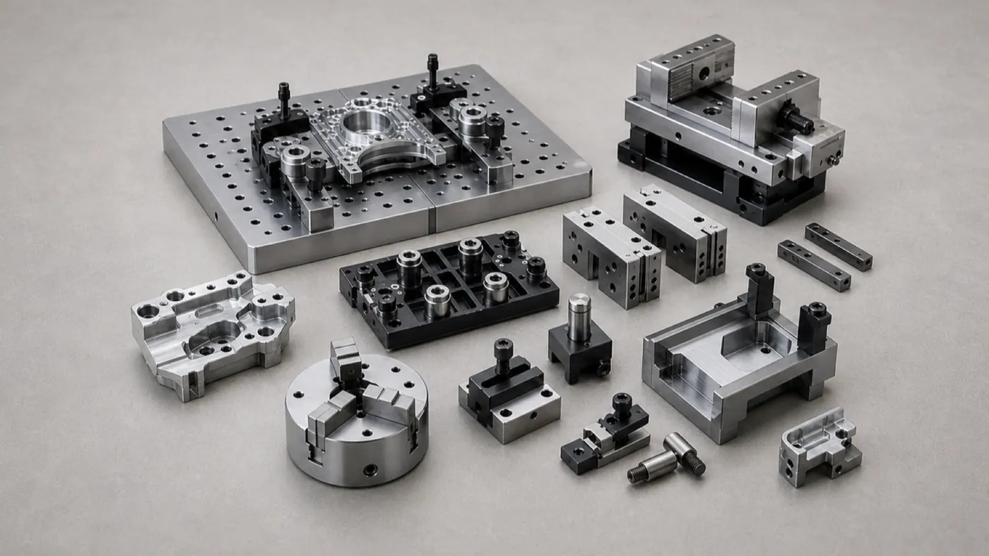
Automation Equipment Automation Gripper Baseplate — Dowelled 6061 Tooling Plate
A 6061-T6 gripper baseplate with an H7 dowel grid, sensor pockets, and hardcoat anodize, built as a repeatable, wear-resistant mounting base for high-cycle end-of-arm tooling.
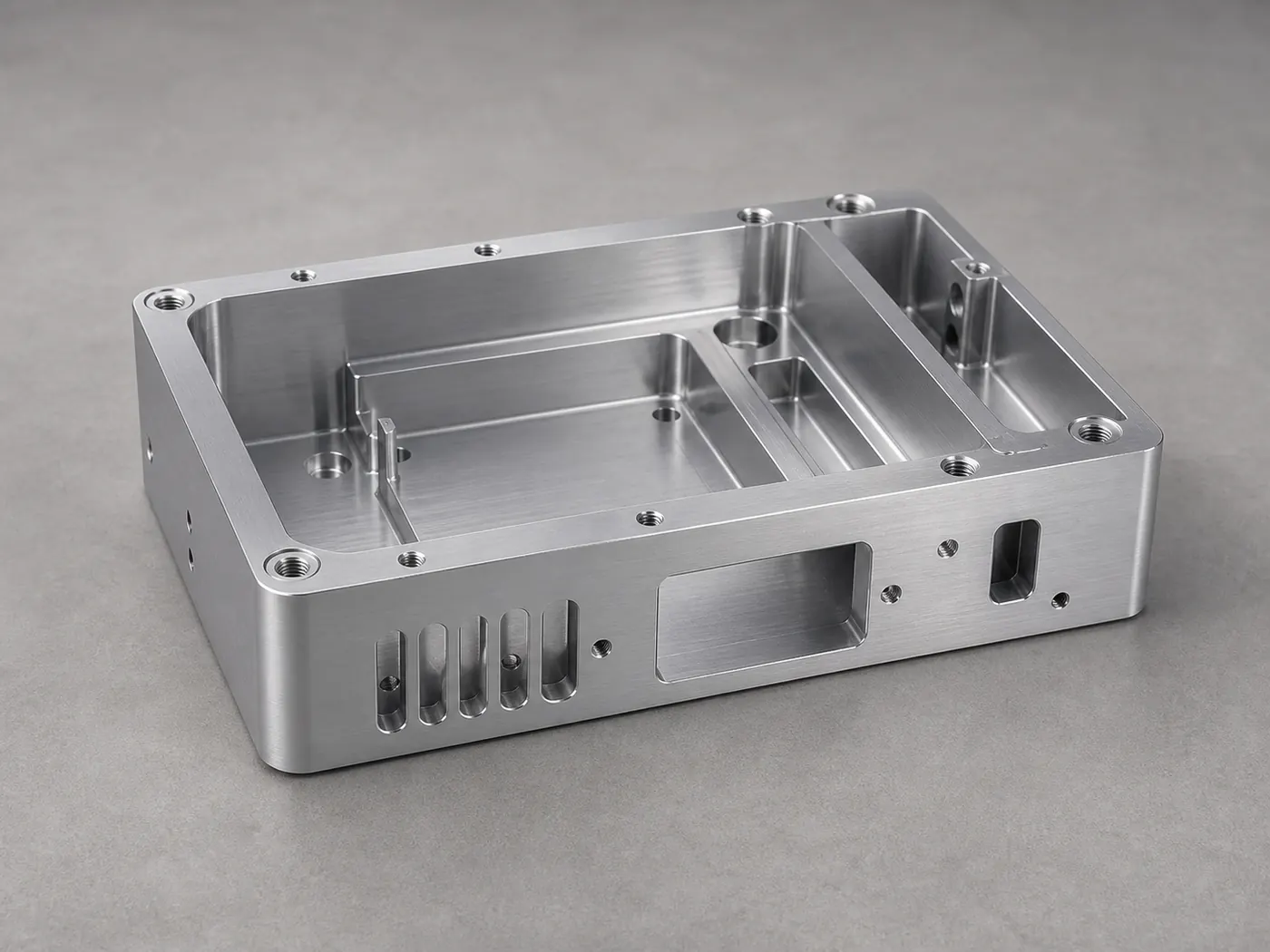
Electronics Aluminum Electronics Housing — 6061-T6 Instrument Enclosure
A pocketed 6061-T6 instrument enclosure with connector cutouts, standoff bosses, and conductive grounding pads, machined and finished for a low-volume electronics build.
Browse the full engineering portfolio in the aluminum CNC machining case studies hub.
Have a similar part? Get it quoted by an engineer
Upload your CAD model and drawing with alloy, finish, and tolerance notes. We review manufacturability before quoting — not after the parts are on the machine.
- Engineering review within one business day
- Prototype to production
- Material certificates available
- ISO 9001 quality management