
Survives coolant, solvents, disinfection cycles, and UV — everything that destroys printed labels.
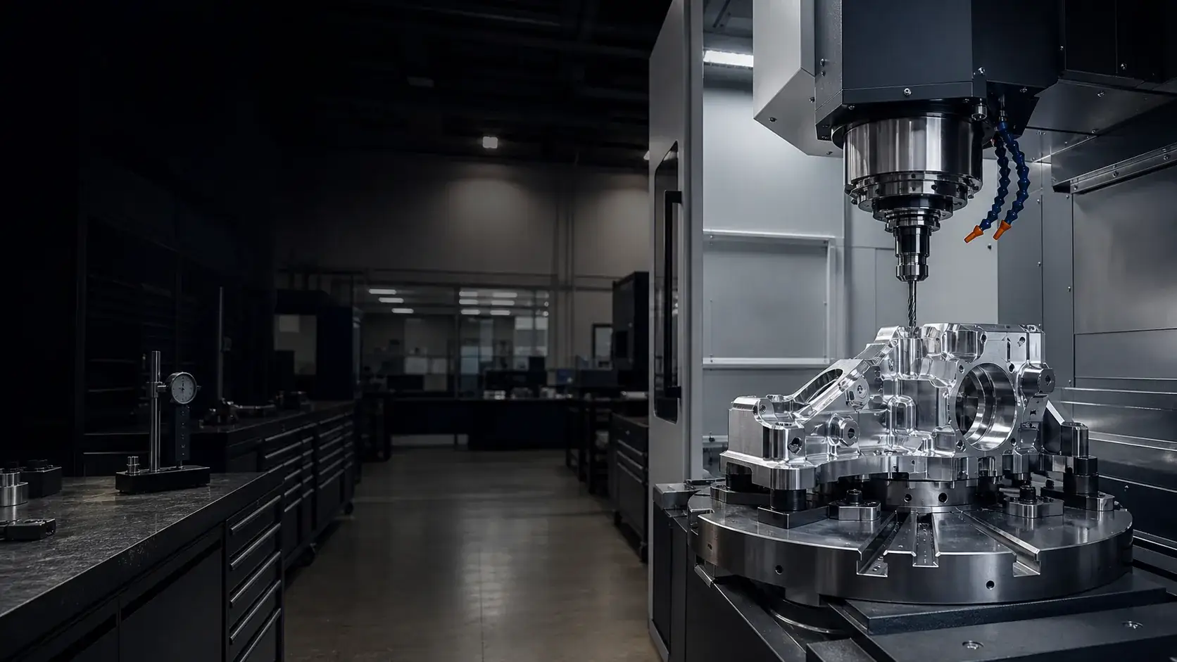
Laser marking & engraving
Laser Marking & Engraving on Aluminum
Every serious part carries identification — part numbers, revisions, serials, legends, logos. Laser marking puts them on aluminum permanently, without inks, labels, or adhesives that fall off the first time coolant or a disinfectant wipe touches them.
We mark as part of the machining-and-finishing sequence, which is why the mark lands exactly where CAD says, in the contrast method that matches your finish.
What this finish is
Four marking methods, one spec decision
A fiber laser modifies the aluminum surface locally — and what it produces depends on the surface it hits. On bare aluminum, the practical options are dark annealing-style marks or engraved (vaporized) grooves. On anodized aluminum, the laser bleaches the dye or removes the film, exposing bright silver against the colored field — the highest-contrast, most durable marking system aluminum offers.
The engineering decision is contrast method plus depth: surface marks are fast and smooth; engraving to 0.05–0.2 mm survives abrasion and re-finishing. CNC engraving with a cutter is the third cousin — deeper, chunkier, right for fixture IDs and castings-style permanence.
- On black/colored anodize
Laser-bleached silver graphics — crisp, permanent, the front-panel standard. - On bare aluminum
Dark oxide marks or engraved grooves; contrast is moderate and improves with surface prep. - Depth options
Surface marking (µm-scale) for cosmetics; engraving 0.05–0.2 mm where marks must survive wear. - Resolution
Text legible to ~0.8 mm character height; logos, 2D codes, and scales reproduce cleanly. - Dimensional impact
None for surface marking; engraving depth is a specified feature like any other.
Benefits
Why laser marking replaces labels and inks
Identification that is part of the part — not attached to it.
Serials, date codes, and 2D data-matrix codes marked per piece support real production traceability.
Silver-on-black legends read at a glance and never rub off — the cleanest panel graphics available.
No label stock, no adhesive aging, no silk-screen tooling — art comes straight from your CAD.
UDI-style codes, CE marks, and safety symbols applied permanently at the size and placement your compliance requires.
Surface marks add no stress risers when kept off fatigue-critical zones — unlike stamping.
Typical applications
What we mark, and for whom
Marking rides on nearly every production order — these are the patterns.
Legends, scales, and logos bleached into black anodize on test and measurement hardware.
UDI-style codes and symbols that survive disinfection — where labels are a compliance liability.
Joint IDs, axis labels, and torque callouts marked where technicians look during service.
Tool numbers, positions, and calibration IDs engraved into plates — the audit trail that can't peel.
Per-piece serials and date codes tied to material lots for warranty and recall traceability.
Logos and model marks on consumer-adjacent enclosures, matched to the cosmetic finish.
Design considerations
Specifying marks that come out right
Marking problems are almost always specification problems — placement, sequence, and contrast decided too late.
Model the mark location, size, and content as a drawing feature. 'Mark P/N somewhere visible' produces somewhere you didn't mean.
Black anodize: mark after coating (bleached silver). Bare or clear parts: mark after machining, before any coating that would cover it. We plan this — but the drawing should state the finish stack.
Even shallow marks are geometry. On fatigue-rated parts, place identification on low-stress bosses and flanges — never in fillets or load paths.
Minimum ~0.8 mm character height for legibility, 1.5 mm+ for marks read at arm's length. 2D codes need a quiet zone — leave flat clearance around them.
Surface marks for panels and cosmetics; 0.1–0.2 mm engraving for tooling and parts that get re-blasted or re-coated later.
Fixed text lives on the drawing; serials and date codes need a stated format (e.g., YYWW-####) so batch one and batch fifty agree.
Compatible aluminum grades
Marking behavior by alloy and finish
The finish matters more than the alloy — contrast comes from what the laser interacts with.
| Alloy | Suitability | Engineering notes |
|---|---|---|
| 6061-T6 | Excellent | Best-in-class under black anodize; good dark marks on bare metal |
| 7075-T6 | Very good | Marks cleanly bare or anodized; engraving stays crisp in the hard surface |
| 5052-H32 | Good | Soft surface favors laser over mechanical engraving; anodize first for contrast |
| 2024-T351 | Good | Mark on low-stress zones only for fatigue-rated parts; coat after marking bare metal |
| MIC-6 | Very good | Engraved IDs and grid coordinates are standard practice on tooling plate |
Comparing coatings instead? Return to the aluminum surface finishes hub or read the full anodized aluminum CNC machining guide.
Related products
Where marking completes the part
The product families where identification is part of the specification.
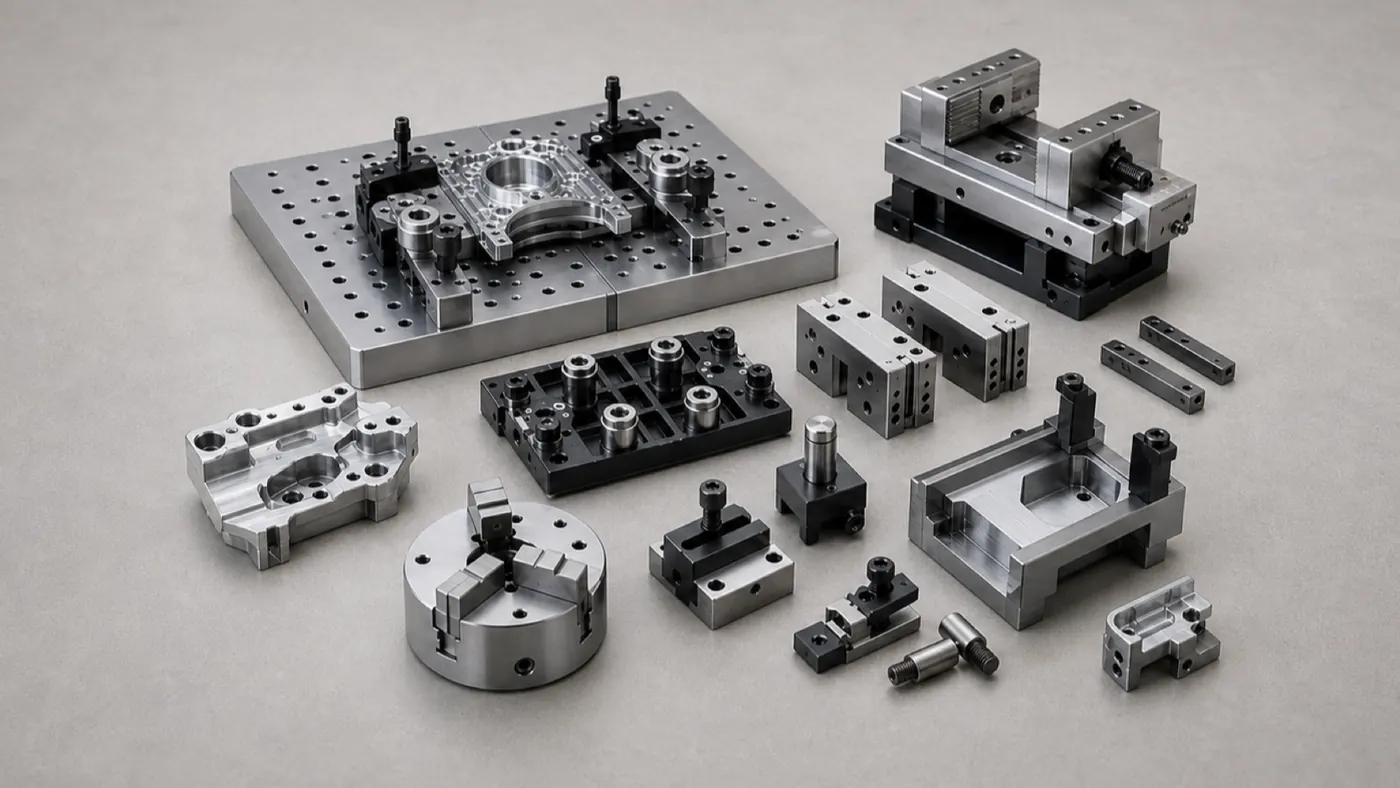
Aluminum CNC fixtures, soft jaws & tooling
Engraved tool numbers and position IDs — traceability that survives shop-floor life.
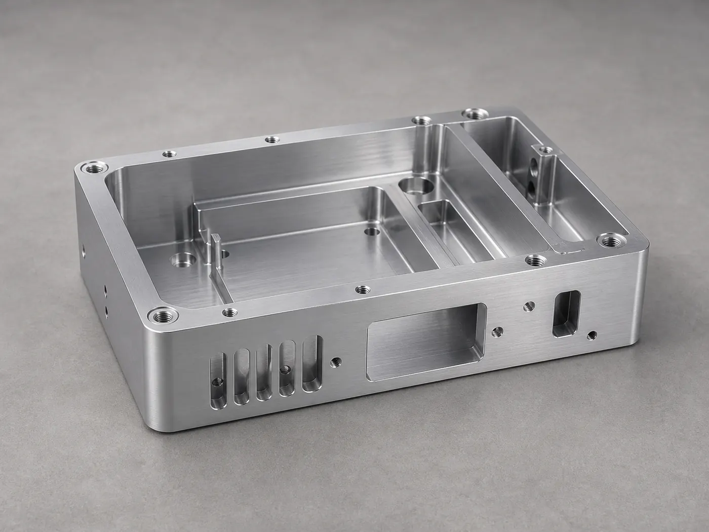
Aluminum CNC machining for electronics housings
Front panels and enclosures with bleached-anodize legends and logos.
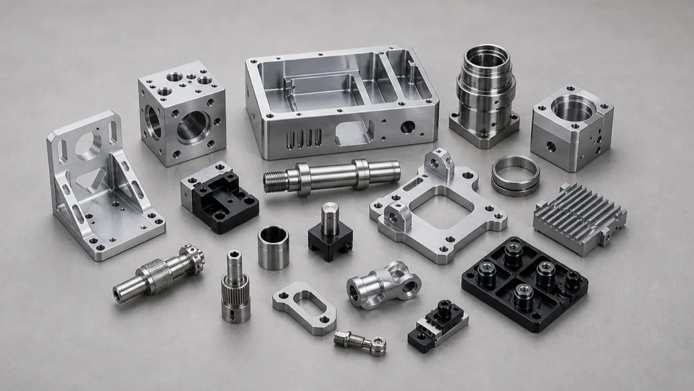
Aluminum CNC machining for medical device hardware
Permanent UDI-style identification that survives disinfection cycles.
Case studies
Case studies with this finish
Aluminum CNC projects that use this surface finish — with specifications, engineering challenges, and inspection notes.
Browse the full engineering portfolio in the aluminum CNC machining case studies hub.
Quote your marked aluminum parts
Send CAD with mark locations, content, serial format, and the finish stack. An engineer confirms contrast method and sequencing with the machining quote — within one business day.
- Machining and finishing under one PO
- Engineering review within one business day
- Masking planned at CAM
- ISO 9001 quality management