
Type II film turns reactive aluminum into a stable oxide barrier — the difference between a part that stains in months and one that looks the same in years.
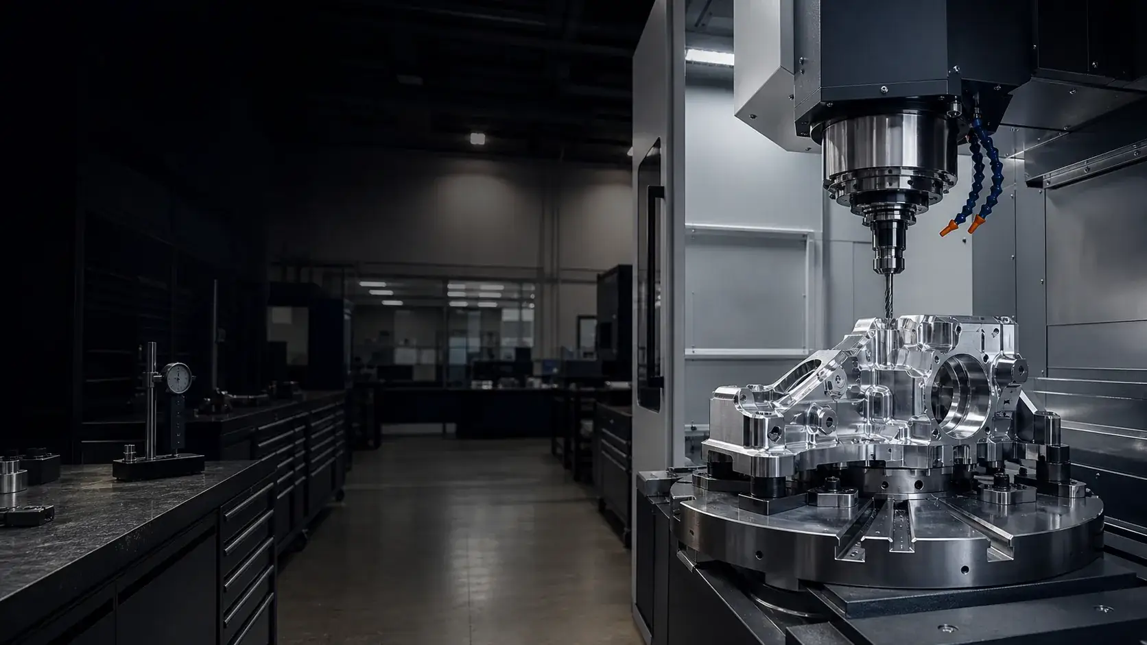
CNC machining + anodizing, one process
Anodized Aluminum CNC Machining
Anodizing is not a step that happens after machining — done right, it's designed into the machining. Film growth lands on your tolerances, racks touch your surfaces, and alloy choice decides your color.
We machine and coordinate anodizing as one process: dimensions compensated for film thickness, masking planned at CAM, and racking points agreed before the first chip is cut.
- ISO 9001:2015
- Prototype to production
- FAI reports available
- Material certificates available
- Engineering review within one business day
What it's best for
What anodizing does for machined aluminum
An anodic film is grown from the part's own aluminum — it's converted surface, not applied coating. That's why it doesn't peel, and why it changes dimensions.
Type III hardcoat reaches hardness comparable to hard chrome, making aluminum viable for sliding surfaces, pivots, and repeated fastening.
Uniform matte or satin color — clear, black, or dyed — that survives handling, UV, and cleaning far better than paint on housings and consumer hardware.
Anodic film is dielectric: useful for isolating mounting faces, and a trap when you forget the grounding pad — masking handles both.
Bead-blasted black anodize is the standard interior for optical cavities, camera bodies, and laser hardware.
Sealed anodize withstands repeated chemical cleaning — standard for medical device and lab equipment surfaces.
Common CNC machined parts
Parts we machine and anodize as one job
Most of our anodized work is 6061 — the alloy anodizing loves — with 7075 and 5052 handled with their own color expectations.
Clear and black anodized electronics housings — the highest-volume anodized part family we ship.
Camera bodies, lens mounts, and cavity interiors bead-blasted and black anodized for reflection control.
Bushings, guide plates, and pivots where Type III film carries the sliding load on aluminum.
Visible machine hardware in matched clear or black across whole assemblies.
Cosmetic-grade anodized parts with controlled texture, tone, and per-batch color consistency checks.
Sealed, dyed anodize on instrument parts with cleanability and marking requirements.
Buying for a specific industry? See how this material fits robotics, automation equipment, medical device hardware, aerospace tooling, electronics housings, and industrial equipment programs.
Machining considerations
Machining decisions that determine anodizing quality
Anodize amplifies the surface it grows on. Most 'anodizing defects' customers see were machined in — here's what we control, and what your drawing should say.
Anodize adds roughly half its film thickness per surface: a Ø10 H7 bore hardcoated at 50 µm shrinks ~0.05 mm. We machine compensated dimensions — but only if the drawing states whether sizes apply before or after coating.
Tool marks, blend lines, and handling scratches all remain visible under Type II film. Cosmetic faces get finishing passes and protected fixturing; bead blasting before anodize is the reliable equalizer.
6061 anodizes bright and uniform; 7075 runs darker with a yellow-grey cast; 2024 goes grey; castings go mottled. Never mix alloys on one visible face and expect a color match.
Every part hangs on a rack that must touch bare metal — leaving a small unanodized witness mark. We agree the location with you (inside a bore, under a label, on a hidden face) instead of letting the anodizer choose.
Anodic film can't follow a knife edge — it cracks and looks like a defect line. Edge breaks of 0.3–0.5 mm minimum, and real chamfers on hardcoat parts, keep film continuous.
Color varies slightly between anodizing lots. Parts that sit side by side in the product should be machined and anodized in the same batch — tell us which parts form a visible set.
Surface finishing
The anodizing menu, specified like an engineer
This is the level of detail that makes an anodizing callout unambiguous — type, film, masking, and appearance, each stated rather than assumed.
8–15 µm typical film. The general-purpose spec: corrosion protection, subtle satin silver, negligible dimensional impact on ±0.02 mm features.
Same film, dye added before sealing. Black is the stable production color; bright dyes (red, blue, gold) fade under UV — confirm outdoor exposure before specifying them.
25–75 µm engineered film, HV 350–500. Specify film thickness and whether dimensions are pre- or post-coat; natural hardcoat runs grey-bronze, dyeable to black.
Write it explicitly: 'Type II, 10–15 µm' or 'Type III, 50 µm ±10%'. 'Anodize' alone leaves the finisher to choose — and thickness drives both protection and fit.
Tapped holes and precision bores are masked by default on hardcoat (film would change fit and embrittle threads). On Type II, threads can be coated if you accept slight fit tightening — state your preference.
Grounding pads, EMI gasket lands, and bonding surfaces get masked bare or chem-filmed after anodize. Mark them in CAD — a fully anodized housing is a fully insulated housing.
Specify an allowed rack-contact zone on the drawing ('rack mark permitted in Ø8 bore only'). It converts an aesthetic surprise into a controlled feature.
For cosmetic programs we hold one alloy, one surface prep, and one anodizing house per part family, with boundary samples agreed at first article.
Define inspection distance and lighting ('no visible defects at 45 cm under office light') instead of 'perfect surface' — it's inspectable and quotable.
Each finish has its own engineering guide: as-machined, bead blasted, clear anodized, black anodized, hardcoat anodized, chem film, and laser marking — or compare them all in the surface finishes hub.
Tolerance & inspection
Dimensional and inspection guidance for anodized parts
The tolerance conversation on anodized parts is really a film-thickness conversation. These are the numbers that matter.
| Feature | Typical capability | Engineering notes |
|---|---|---|
| Type II film thickness | 8–15 µm typical | Dimensional growth ~half of film per surface — usually inside ±0.02 mm budgets |
| Type III film thickness | 25–75 µm, specified | Ø changes by ~film thickness on bores/shafts; we machine compensated |
| Critical fits (H7 bores, bearing seats) | Held post-coat | State 'dimensions after anodize' on the drawing; masked where film is unwanted |
| Threaded holes | 6H post-mask | Masked on hardcoat by default; Type II over threads by agreement |
| Flatness of sealing faces | Unchanged by Type II | Hardcoat on large faces can add measurable stress — reviewed per part |
| Cosmetic / FAI inspection | Boundary samples + documented FAI | Color, gloss, and defect standards agreed at first article, then held per batch |
Before you upload CAD
Anodizing checklist before you upload CAD
Six callouts that make an anodized-part RFQ complete. Most anodizing disappointments trace back to one of these being unstated.
- State type, color, and film thickness
'Type II black, 10–15 µm' or 'Type III natural, 50 µm' — the full spec in one line on the drawing title block. - Mark cosmetic surfaces and grade
Identify class-A faces and the viewing standard; everything else defaults to functional finish. - List masked features
Threads, precision bores, grounding pads, and press-fit zones — each either masked, compensated, or accepted as coated. - Say whether dimensions are pre- or post-coat
One note resolves every fit question: 'All dimensions apply after anodizing' is the usual right answer. - Approve a racking zone
Pick the surface where a bare contact mark is acceptable — or tell us there isn't one, and we'll plan plugged-hole racking. - Note sets that must color-match
Group part numbers that appear together in the product so we batch them through anodize as one lot.
Related product applications
Product families we anodize most
Anodizing guidance in context — each product guide covers the finish selection for its part family.
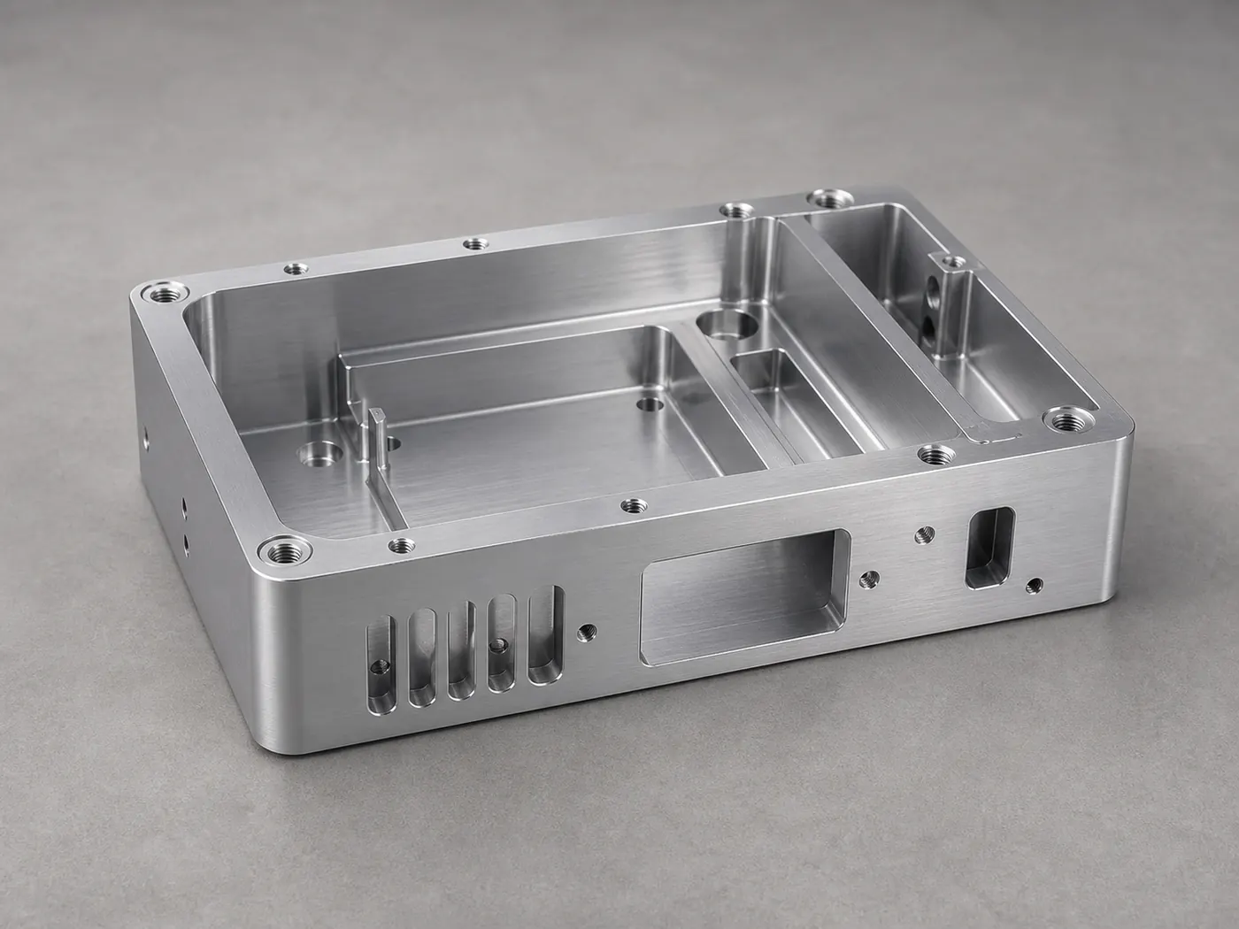
Aluminum CNC machined housings & enclosures
Clear and black anodized enclosures — the deepest overlap with cosmetic anodizing.
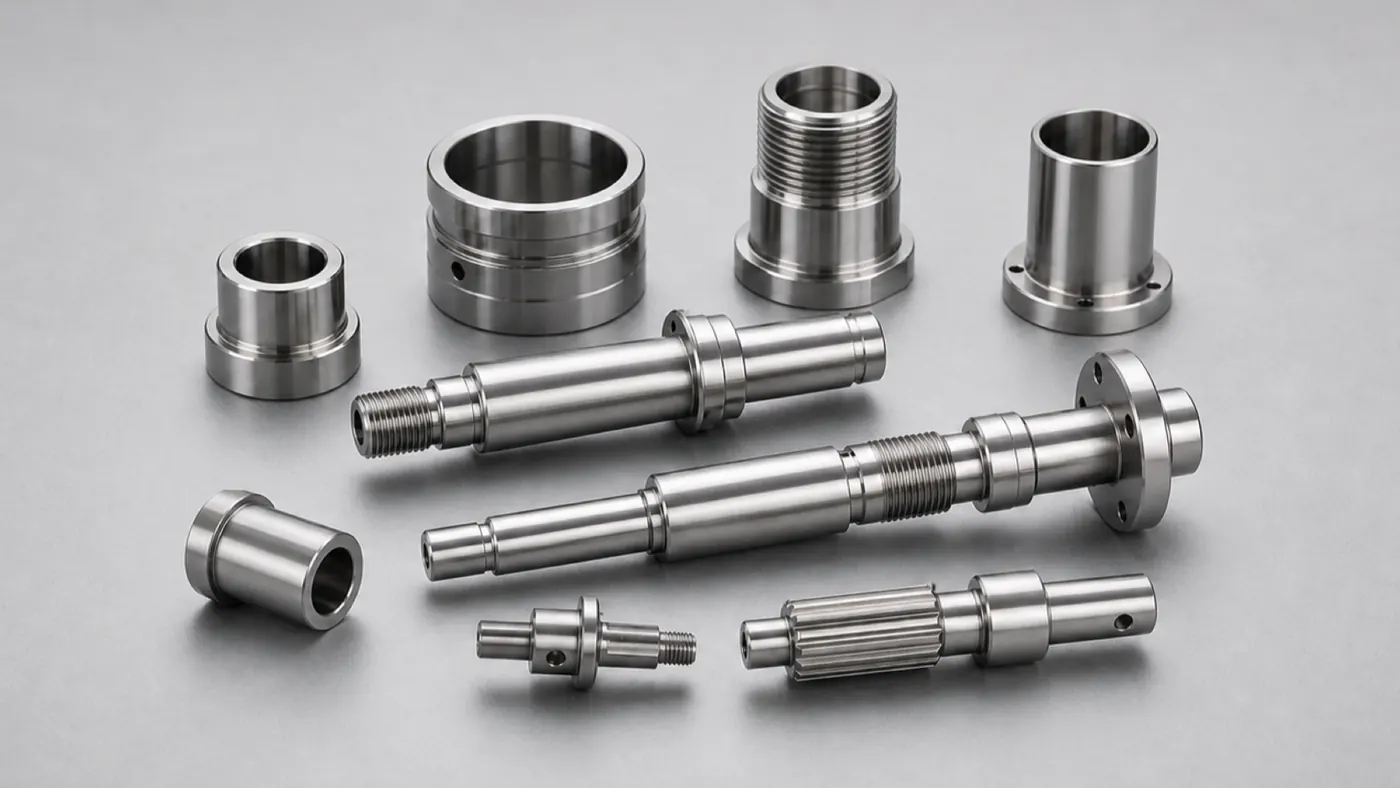
Aluminum CNC turned shafts & bushings
Hardcoat anodized wear surfaces with post-coat fits on turned hardware.
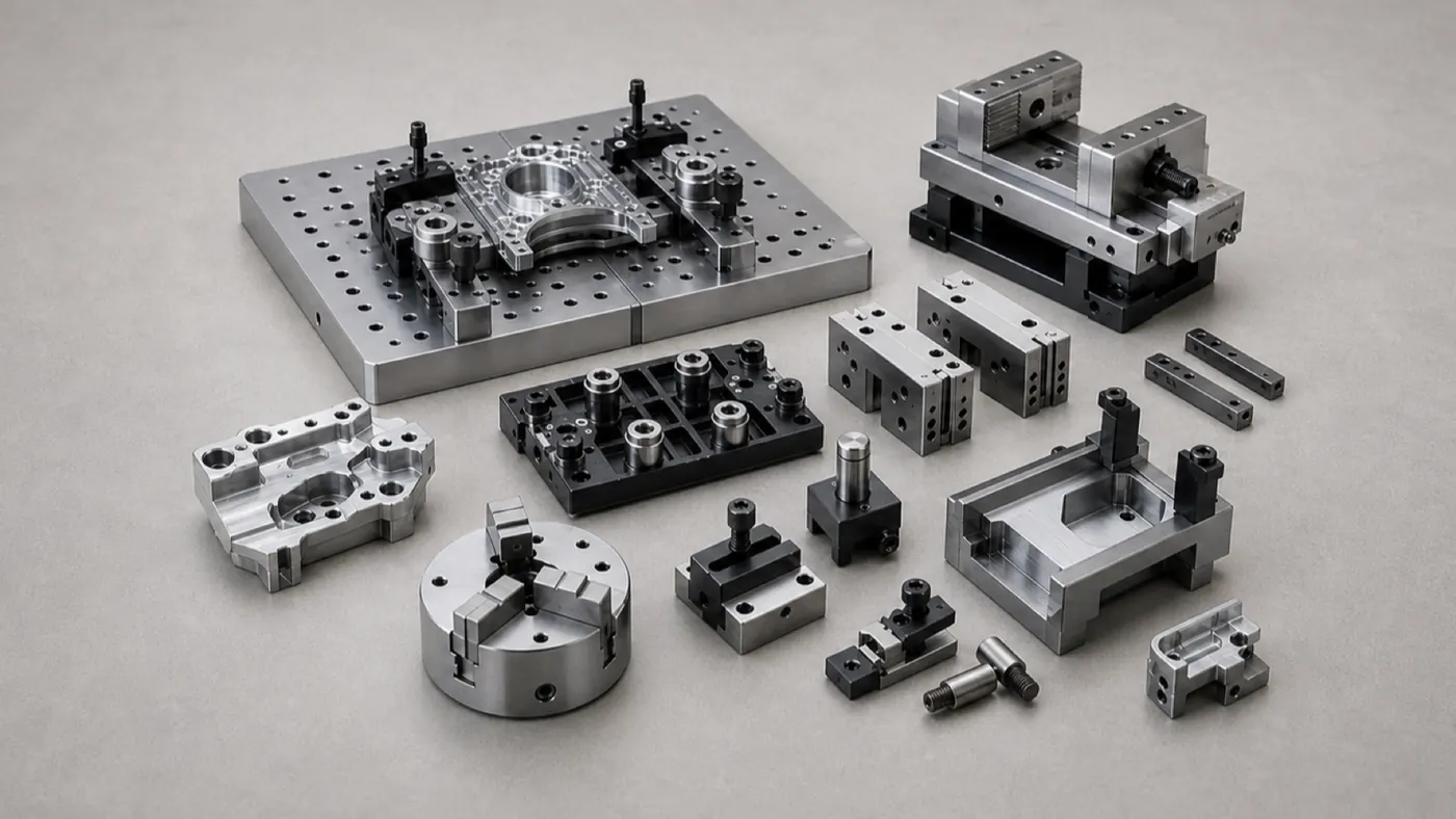
Aluminum CNC fixtures, soft jaws & tooling
Hardcoated locating surfaces and color-coded fixture families.
Quote your anodized aluminum parts
Send STEP models and PDF drawings with anodize type, film thickness, masking, and cosmetic notes — or send what you have and an engineer will draft the finishing spec with you. Review within one business day.
- STEP or IGES models
- PDF drawings with critical dimensions
- Alloy, temper, and finish notes
- Target quantity and timeline