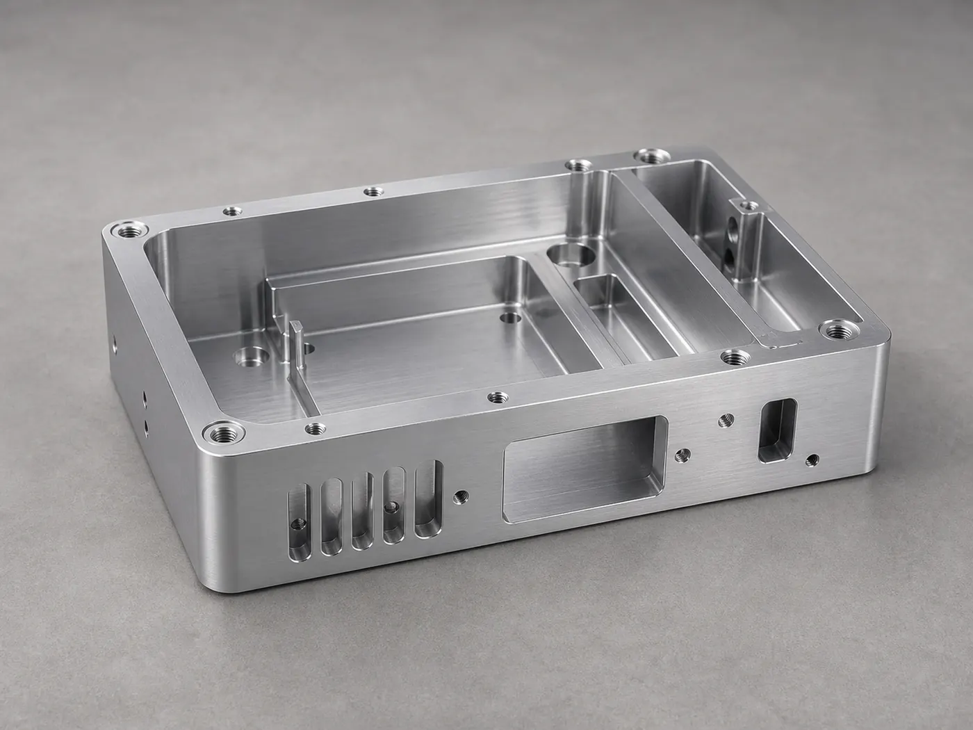
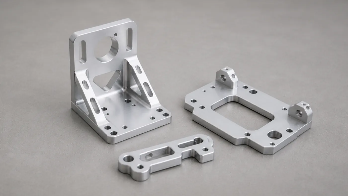
Engineering capabilities

Engineering Capabilities for Custom Aluminum CNC Machining

This is an engineering reference for the aluminum CNC machining we run in-house — milling, turning, finishing, and inspection. Use it to judge whether we can hold your part's tolerances, features, and finish before you send an RFQ.

We machine 6061, 7075, 2024, 5052, and MIC-6 aluminum from prototype through low-volume production, with DFM feedback and an engineering review of your drawings within one business day.

  • ISO 9001:2015
  • Prototype to production
  • Engineering review within one business day
  • Material certificates available
  • FAI reports available
CNC machining capability overview

Milling, turning, and secondary processes for aluminum

Every process below is chosen for a reason. This is how we decide which one fits your aluminum part, its features, and its tolerance requirements.

3-axis CNC milling

Milling on X, Y, and Z for prismatic aluminum parts — plates, brackets, covers, and housings with features approached from the top and sides.

Typically selected forFlat-faced, accessible geometry where features sit on one or two planes. The most cost-effective route for the majority of aluminum parts.

4-axis CNC milling

Adds an indexing or continuous rotary axis so the part turns to present new faces without a manual re-fixture.

Typically selected forRadial features, cross-drilling around a bore, and multi-face parts where a fourth axis removes setups and protects feature-to-feature position.

5-axis CNC milling

Positions the tool at compound angles (3+2) or moves five axes together for contoured surfaces and deep, angled reach with short, rigid tools.

Typically selected forComplex contours, angled bosses, and multi-face parts that would otherwise need several setups — improving accuracy and shortening lead time.

CNC turning

Turning of round aluminum stock for concentric features, with live tooling for cross-holes, flats, and slots on the same setup.

Typically selected forShafts, bushings, spacers, standoffs, and threaded parts where concentricity, roundness, and turned diameters are the driving requirement.

Secondary machining

Tapping, reaming, boring, cross-drilling, chamfering, engraving, and controlled deburring after the primary milling or turning operation.

Typically selected forPrecision holes, threaded features, and edge conditions that are best cut or finished as a dedicated, repeatable operation.

Assembly support

Installation of threaded inserts, dowel pins, and hardware, plus light sub-assembly, kitting, and pre-fit checks before parts ship.

Typically selected forParts that arrive ready to build — where press-fit inserts, helicoils, or mated components reduce work on your line.

Equipment capability table

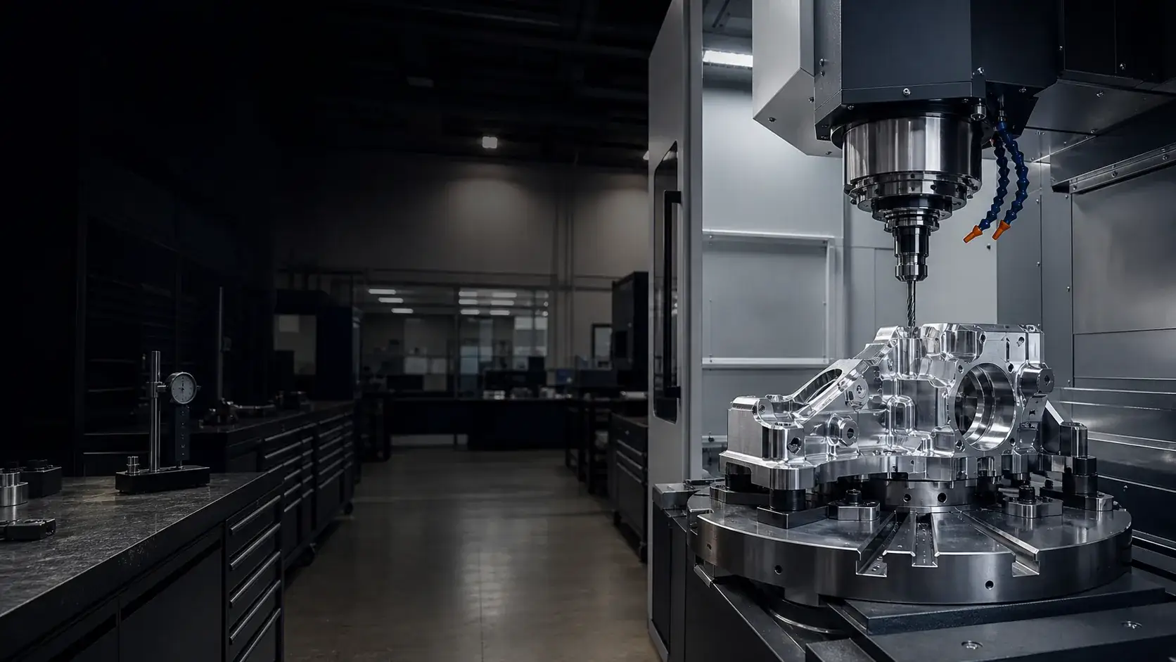
Machining capability at a glance

A quick engineering summary of what we support. Values marked to be confirmed are left for verified factory specifications so nothing here is invented.

CapabilityOur support
CNC milling 3-axis, 4-axis, and 5-axis aluminum milling
CNC turning Shafts, bushings, spacers, standoffs, and threaded turned parts with live tooling
Maximum part size To be confirmed Milling envelope and turning swing × length
Minimum feature size To be confirmed Smallest cutter diameter and slot / wall capability
Supported threads Metric, UNC, UNF, NPT, and custom threads — cut, formed, or thread-milled
Surface roughness To be confirmed Achievable Ra by process (as-machined and finished)
Typical tolerance General ±0.05 mm; fine aluminum features to ±0.005 mm (geometry-dependent review)
Inspection equipment CMM, height gauge, micrometer, thread gauges, and calipers
Aluminum alloys 6061, 7075, 2024, 5052, MIC-6, and customer-specified grades
Documentation Material certificates, FAI reports, and dimensional reports on request

Tolerances and finishes depend on geometry, aluminum alloy, and inspection method — we flag risk before machining starts. See the aluminum grade machining guides and surface finishes hub for feature-level detail.

Aluminum machining expertise

The manufacturing challenges we routinely solve

Aluminum is fast to cut but unforgiving to control. These are the problems that separate a part that measures in from one that warps, burrs, or drifts — and how experienced machining keeps yours reliable.

Thin-wall aluminum machining

Why it's demanding

Walls below roughly 1 mm deflect under cutting and clamping forces, causing chatter, taper, and dimensional drift — worsened by aluminum's low stiffness.

Engineering considerations

Wall-to-height ratio, tool engagement, climb milling, a finishing allowance, and low-stress fixturing all set the achievable thickness.

How we hold it

We sequence roughing and finishing, leave adaptive stock, and take light finishing passes with sharp tooling to hold flat, parallel walls without deformation.

Deep pocket machining

Why it's demanding

Deep pockets force long tool overhang, which reduces rigidity and invites deflection, a poor floor finish, and chip-evacuation problems.

Engineering considerations

Depth-to-diameter ratio, corner radii sized for the largest usable tool, ramping strategy, and coolant or air blast for chip clearing.

How we hold it

We select the shortest viable tool stack-up, step down in controlled passes, and open generous corner radii in DFM to keep floors flat and walls straight.

Flatness control for aluminum plates

Why it's demanding

Rolled aluminum plate carries residual stress; removing material unbalances it and the part bows after machining.

Engineering considerations

Stock choice (cast tooling plate such as MIC-6 vs. rolled), stress relief, symmetric material removal, and vacuum or low-clamp fixturing.

How we hold it

We recommend pre-stabilized plate, machine both faces to balance stress, and re-check flatness before final passes to hold tight datums.

Warping control after machining

Why it's demanding

Heat, clamping load, and unbalanced stock removal lock stress into the part, which releases as warp once it leaves the fixture.

Engineering considerations

Separating roughing and finishing, rest periods, reduced clamping pressure, and coolant strategy to limit thermal gradients.

How we hold it

We rough with stock left on, relieve clamps, let the part settle, then finish — keeping long, thin aluminum parts within tolerance.

Burr control on threaded aluminum parts

Why it's demanding

Soft, ductile aluminum raises burrs at hole entries, thread crests, and intersecting features, affecting fit, sealing, and cosmetics.

Engineering considerations

Tap selection, cut tap vs. thread mill, entry chamfers and countersinks, and deburr access for cross-holes.

How we hold it

We add entry chamfers, thread-mill where finish matters, and apply controlled manual and tumbling deburr so threads gauge cleanly and edges stay safe.

Cosmetic surface protection

Why it's demanding

Aluminum scratches and dents easily; handling marks, fixture witness, and tool lines show badly on parts that will be anodized or left visible.

Engineering considerations

Identifying A-surfaces, grain direction, fixturing off non-cosmetic faces, and protected handling between operations.

How we hold it

We map cosmetic surfaces at quoting, protect them through machining and finishing, and route contact points away from visible faces.

Tight tolerance features

Why it's demanding

Bores, bearing seats, and mating interfaces at ±0.01 mm and tighter demand thermal, tool-wear, and metrology control that general tolerances do not.

Engineering considerations

Which dimensions are truly critical, reaming or boring vs. milling, temperature-stable finishing, and in-process gauging.

How we hold it

We isolate critical features, finish them as dedicated operations, and verify with calibrated gauges and CMM before release.

Precision hole positioning

Why it's demanding

True-position callouts on hole patterns stack fixturing, spindle, and datum error; loose control causes assembly misalignment.

Engineering considerations

Datum scheme, single-setup drilling where possible, spot-drilling, and rigid tapping to hold position and perpendicularity.

How we hold it

We work from clear datums, drill patterns in one setup, and inspect true position so bolt patterns and dowels align first time.

Large aluminum plate machining

Why it's demanding

Large plates are hard to hold flat, prone to stress-induced movement, and challenge machine travel and repeatability across the surface.

Engineering considerations

Bed support, multi-zone clamping, part envelope vs. machine travel, and flatness measured across the full field.

How we hold it

We plan support and clamping to keep large plates stable, machine in balanced passes, and verify flatness across the whole part.

Multi-axis machining for complex geometries

Why it's demanding

Compound angles, contoured surfaces, and features on many faces are setup-heavy on 3-axis alone, and multiple setups introduce stack-up error.

Engineering considerations

3+2 positioning vs. simultaneous 5-axis, tool reach and collision clearance, and consolidating setups to protect accuracy.

How we hold it

We use 4- and 5-axis work to reach features in fewer setups, improving accuracy between faces and shortening lead time on complex parts.

Surface finish considerations

Finishing options and the engineering behind them

Finish is part of the specification, not an afterthought. Here is what each option delivers on aluminum — and the concerns that decide whether it looks and fits right.

Clear anodizing (Type II)

Adds corrosion and wear resistance while keeping a natural metallic look — a durable default for most aluminum parts.

Black anodizing (Type II, dyed)

Uniform matte-to-satin black for enclosures, optical parts, and cosmetic hardware where dye consistency matters.

Hard anodizing (Type III)

A thick, dense, wear-resistant layer for sliding surfaces and harsh environments — grows part dimensions, so it is planned in.

Bead blasting

A uniform matte cosmetic texture that hides tool marks; also a common, even pre-anodize preparation.

Sandblasting

Coarser media for a heavier texture, controlled reflectivity, or surface cleaning ahead of finishing.

Brushing

A directional satin grain for a premium look on visible faces, applied along a defined grain direction.

Laser marking

Permanent part numbers, logos, and data-matrix codes with no measurable effect on part dimensions.

Read the finish guides for clear anodized aluminum, black anodized aluminum, hardcoat anodized aluminum, bead blasted aluminum, chem film (Alodine), and aluminum laser marking — or compare them all in the aluminum surface finishes hub.

Common finishing concerns engineers raise

Color consistency after anodizing

Dye lot, alloy, and bath conditions shift shade. We batch parts together and work to a reference sample so color stays consistent across an order.

Film thickness

Type II and Type III build differently and grow dimensions. We account for film build on tight features, threads, and press fits before finishing.

Cosmetic surface requirements

Define A-surfaces and acceptance criteria so cosmetic targets are unambiguous rather than judged part by part.

Thread masking

Threads and reamed bores are masked or specified so film build does not bind fits or change gauge results.

Contact points (racking marks)

Parts hang on racks and leave small unanodized witness marks. We agree rack locations on non-critical areas up front.

Surface preparation before anodizing

Even color needs uniform preparation — machining lines telegraph through thin films, so we blast or etch to a consistent base.

Inspection & quality control

How we verify aluminum parts before they ship

Inspection is scaled to your requirements — from a quick dimensional check to a full FAI with a ballooned report. Tell us what the part demands and we match the method.

First Article Inspection (FAI)

A full dimensional record of the first part against the drawing, used to sign off a new part or a new revision before production.

CMM inspection

Coordinate measuring for true position, profile, flatness, and tight bores where hand tools cannot resolve the tolerance.

Height gauge inspection

Step, height, and datum-referenced dimensions checked on a surface plate for prismatic aluminum parts.

Micrometer inspection

Precise outside diameters, thicknesses, and turned features measured to close tolerance.

Thread gauge verification

Go/no-go plug and ring gauges confirm tapped and turned threads meet class of fit.

Surface finish inspection

Ra verification and cosmetic review against the specified finish, texture, and appearance.

Material certification

Mill certificates trace the aluminum alloy and temper back to the supplied stock when the order requires it.

Dimensional reports

Ballooned drawings with recorded measurements for critical features and customer-defined checkpoints.

Not sure what level of inspection your part needs? Our quality assurance approach explains how FAI, in-process checks, and documentation are selected against your drawing.

Recommended aluminum materials

Commonly machined alloys and when to specify them

Alloy choice drives strength, finish, corrosion resistance, and cost. These are the grades we machine most, with a full engineering guide behind each one.

AlloyWhy engineers specify itTypically selected for
6061 The all-round workhorse — good strength, excellent machinability, weldable, and anodizes cleanly. Brackets, housings, plates, and general structural and enclosure parts.
7075 High strength-to-weight, approaching some steels, with good fatigue resistance. Aerospace tooling, high-load structural parts, and stressed brackets.
2024 High strength and fatigue resistance where its lower corrosion resistance is managed with a coating. Aircraft structure, fittings, and fatigue-critical components.
5052 Excellent corrosion resistance and formability; a marine and sheet-friendly grade. Enclosures, panels, and parts exposed to moisture or chemicals.
MIC-6 Stress-relieved cast tooling plate that stays flat and stable through machining. Base plates, jigs, fixtures, and precision flat references.

Full machining guides: 6061 aluminum CNC machining, 7075 aluminum CNC machining, 2024 aluminum CNC machining, 5052 aluminum CNC machining, and MIC-6 aluminum plate machining.

Design guidelines for engineers

A quick checklist before you upload CAD

A few minutes on the drawing package saves a round of DFM questions and gets you an accurate quote faster. This is what helps us most.

  • Avoid unnecessarily tight tolerances
    Tighten only the dimensions that must be controlled. Blanket tight tolerances raise cost and lead time without adding function.
  • Define critical dimensions clearly
    Call out which features are critical and reference them to clear datums so we measure what matters.
  • Specify cosmetic surfaces
    Mark A-surfaces, grain direction, and appearance acceptance so cosmetic faces are protected and finished correctly.
  • Identify threaded holes
    State thread size, class, depth, and whether inserts are required so tapping and hardware are planned in.
  • Specify anodizing requirements
    Give type, color, and any masking or thickness limits — film build affects tight features and fits.
  • Define flatness where necessary
    Where flatness drives function, state it explicitly so stock, fixturing, and stress relief are chosen to hold it.
  • Include material and temper
    Confirm alloy and temper (for example 6061-T6). Substituting changes strength, finish, and machining behavior.
  • Provide STEP files with PDF drawings
    A STEP (or IGES) model plus a dimensioned PDF drawing lets us quote geometry and tolerances accurately.

Send your drawings — we'll confirm we can make it

Upload your CAD and drawings, or message an engineer directly. We review manufacturability, flag tolerance and finish risk, and reply with next steps within one business day.

  • Prototype to production
  • Engineering review within one business day
  • Material certificates available
  • ISO 9001 quality management