
An enclosure only seals if the gland cross-section and land flatness are right on the first article. We pulled groove dimensions from the seal manufacturer's gland tables rather than inventing a cross-section.
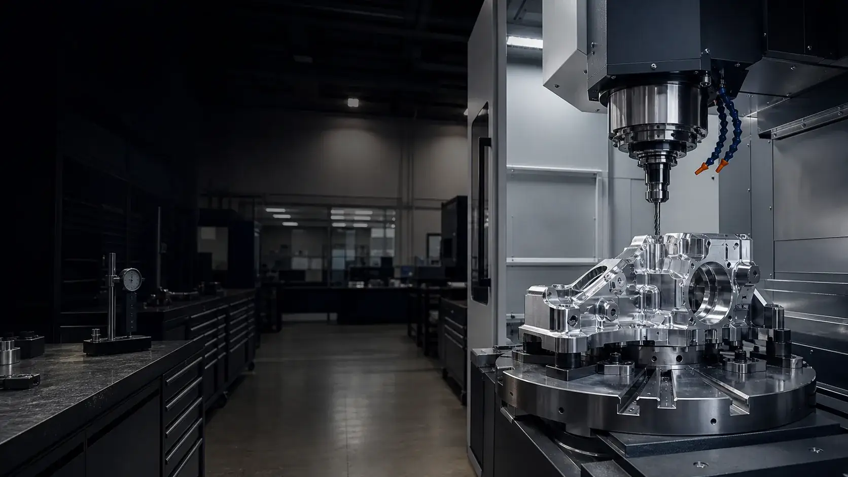
Case study · Aluminum housings
Aluminum Control Module Enclosure — Sealed 6061 Housing
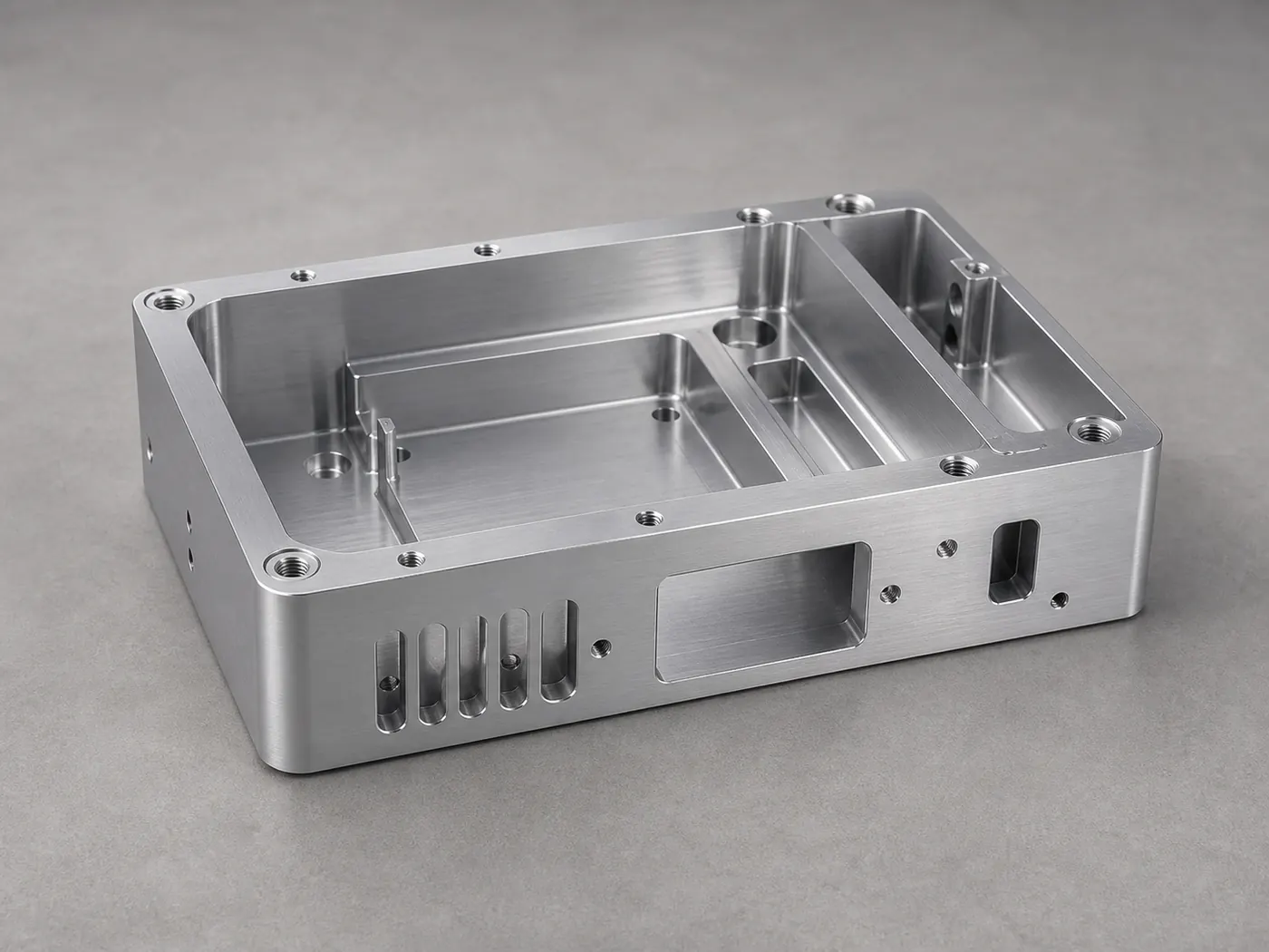
A sealed 6061-T6 control module enclosure with a machined O-ring gland, threaded service bosses, and a bead-blasted black anodize finish for vibration- and coolant-exposed environments.
- 6061-T6
- O-ring gland
- IP-rated seal
Project overview
Project overview
This project is a sealed aluminum control module enclosure — a body with an internal cavity and a removable lid that closes onto a machined O-ring gland. It lives on machinery, so the design has to seal reliably, survive vibration and coolant exposure, and open cleanly for service.
The whole part hinges on the sealing land. It has to stay flat after the body is hollowed out, and the O-ring groove has to match the seal supplier’s gland table exactly. The routing separates roughing from finishing with a stress-relief pause, then finishes the land and gland last so they hold 0.05 mm flatness over 100 mm. Serviced bosses get helical inserts so the threads survive being opened repeatedly.
Bead blast followed by black anodize gives the enclosure a uniform finished look and corrosion protection, with sealing lands masked so anodize growth doesn’t change the gland fit. Dimensions, ingress rating, and volumes are placeholders — the sealing and finishing approach is representative of the sealed housings we machine.
Technical specification
Part specification
Key manufacturing parameters for this project. Values marked as placeholders stand in for confidential production data.
| Parameter | Specification |
|---|---|
| Overall envelope | Placeholder — e.g. 160 × 100 × 60 mm |
| O-ring gland | Machined to AS568 gland tables; width/depth per seal spec |
| Sealing land flatness | 0.05 mm over 100 mm |
| Wall thickness | 2.0 mm nominal for structural rigidity |
| Thread engagement | 1.5×D tapped bosses; helical inserts on serviced threads |
| General tolerance | ±0.05 mm (ISO 2768-f unless noted) |
Engineering challenges
What made this part difficult
The manufacturability risks we planned around before cutting metal.
The sealing land has to stay flat after the body is hollowed out. Roughing, relief, then finishing the land last kept it within 0.05 mm over 100 mm.
Bosses that get opened for service wear out plain aluminum threads, so serviced locations use helical inserts sized for repeated fastening.
Manufacturing process
How the part was made
The routing from raw stock to finished, inspected components.
- Step 1: Engineering review
Confirmed gland dimensions, land flatness callout, and which bosses needed inserts before quoting. - Step 2: Roughing from billet
Bulk pocketing of body and lid with stepped depths to manage tool load and heat. - Step 3: Stress relief
A relief pause before finishing to let roughing stress settle out of the walls. - Step 4: Finish machining
Sealing land, gland, bores, and mating faces finished last to hold flatness and fit. - Step 5: Tapping and inserts
Bosses tapped and helical inserts installed at serviced locations. - Step 6: Finishing and inspection
Bead blast, black anodize, then dimensional and seal-fit sign-off.
Inspection methods
How quality was verified
Dimensional and process controls used to sign off the part. See our full aluminum part inspection process.
Gland width/depth and land flatness checked against the seal spec on a CMM.
Full FAI on the first part with a report available; placeholder for the customer's AQL on the run.
Lid-to-body closure and O-ring compression confirmed before finishing sign-off.
Surface finishing
Finishing and post-processing
Finishing decided alongside the machining plan. Compare options in the aluminum surface finishes hub.
Uniform matte pre-texture that evens out tool marks and gives the anodize a consistent appearance.
Corrosion protection and a clean industrial look for a machine-mounted controller exposed to coolant and handling.
Critical sealing lands masked so anodize growth does not change the gland fit.
Typical application
Where this enclosure is used
Sealed control module enclosures like this house drivers, controllers, and junction electronics that live on machinery — exposed to vibration, coolant mist, and periodic service access.
Machining from billet lets the same design carry a precise seal and survive repeated opening without the tooling cost of a casting.
- Manufacturability review
Every project starts with an engineering review of tolerances, wall thickness, and finish before we quote. - Prototype to production
The same routing scales from a first article to recurring production batches. - Documentation
Material certificates and first article inspection reports are available on request.
Explore the engineering
Related capabilities, materials, and pages
This project connects to our wider aluminum machining program. Start with our engineering capabilities, then dive into the specific products, materials, industries, and finishes involved.
Case studies
More aluminum CNC machining case studies
Projects with comparable materials, tolerances, or finishing requirements.
Electronics Aluminum Electronics Housing — 6061-T6 Instrument Enclosure
A pocketed 6061-T6 instrument enclosure with connector cutouts, standoff bosses, and conductive grounding pads, machined and finished for a low-volume electronics build.
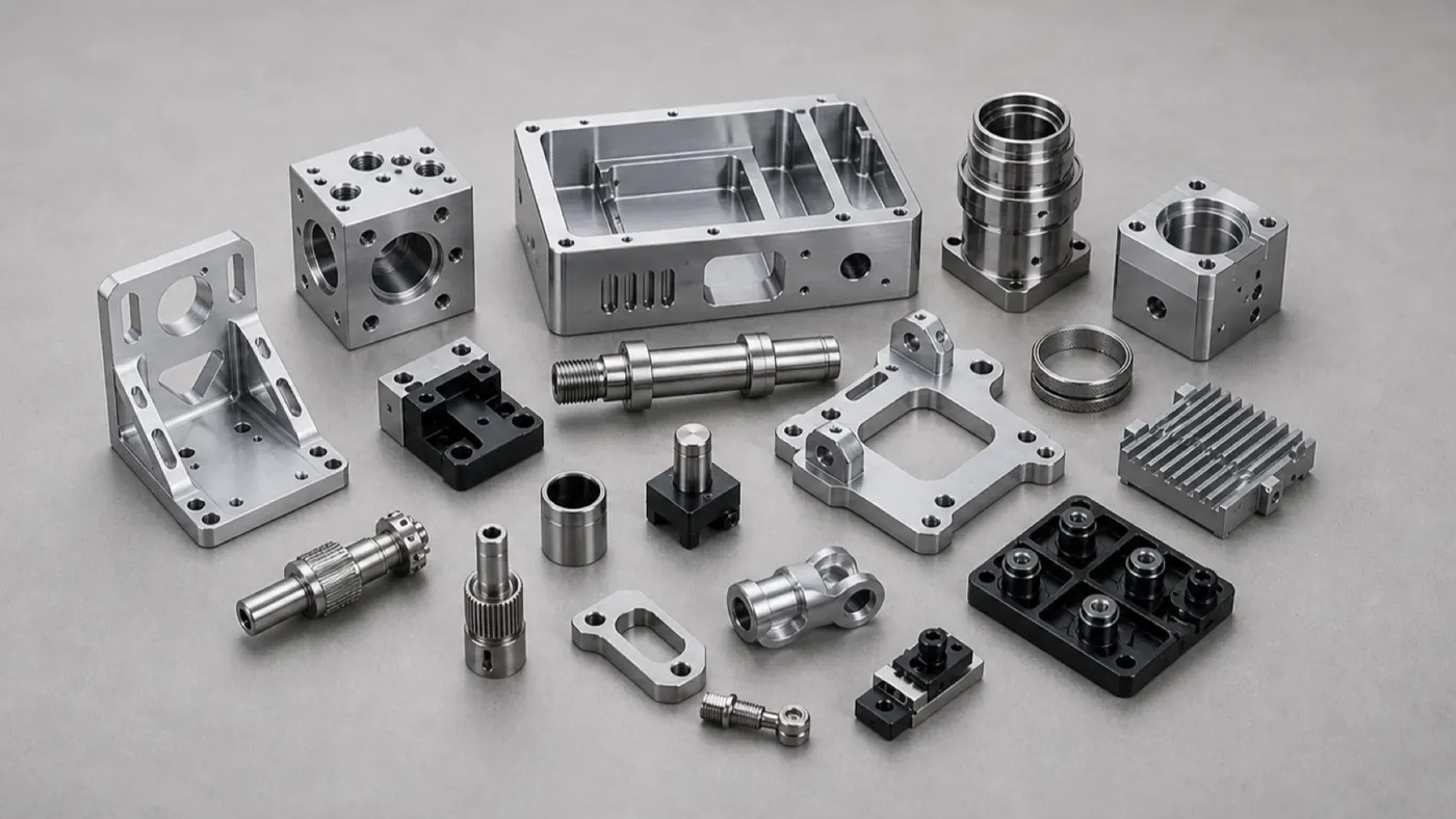
Industrial Equipment Industrial Pump Housing — Machined 6061 Body with Sealed Bores
A 6061-T6 pump housing with concentric bearing bores and sealed internal passages, hardcoat and chem-film finished to survive vibration, wear, and coolant in industrial service.
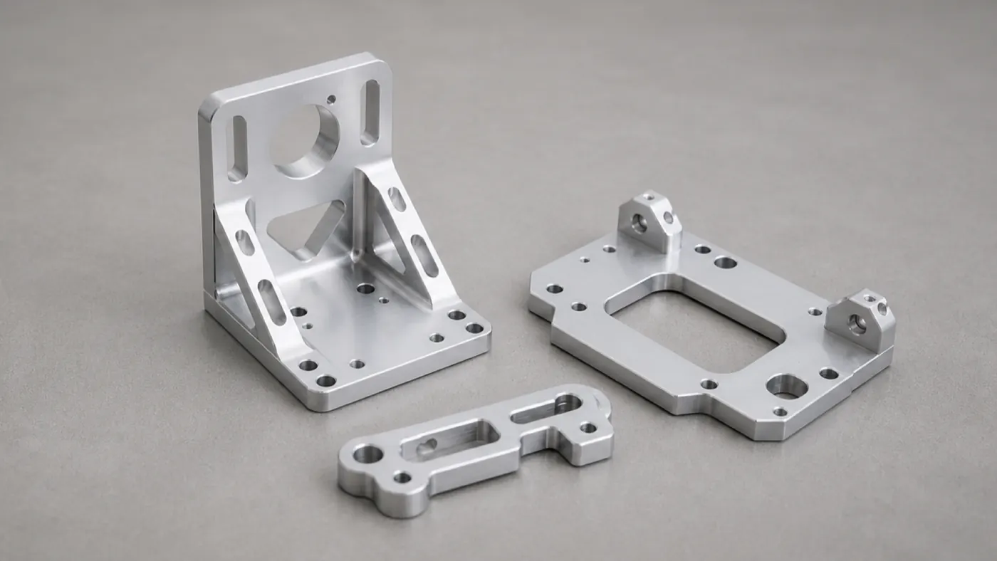
Robotics 7075 Robotic Arm Bracket — Lightweight Structural Link
A 7075-T6 structural arm bracket with lightweighting pockets, precise bearing bores, and hardcoat anodize, machined for stiffness-to-weight in a robotic joint.
Browse the full engineering portfolio in the aluminum CNC machining case studies hub.
Have a similar part? Get it quoted by an engineer
Upload your CAD model and drawing with alloy, finish, and tolerance notes. We review manufacturability before quoting — not after the parts are on the machine.
- Engineering review within one business day
- Prototype to production
- Material certificates available
- ISO 9001 quality management