
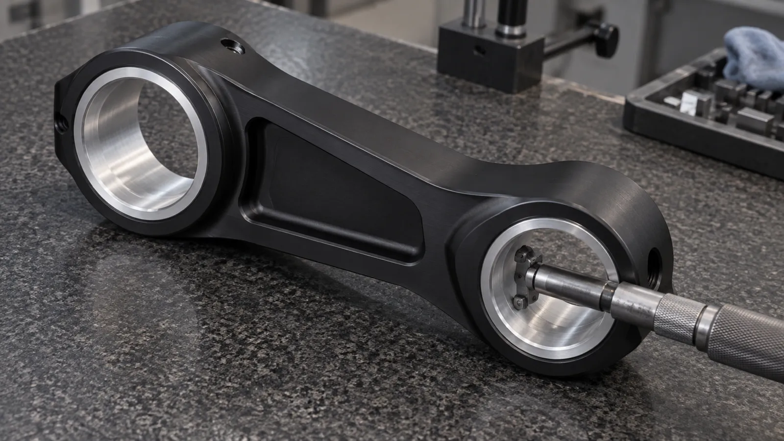
Direct answer: A robotic joint in 7075-T6 is controlled by four things, and only one of them is strength. Bearing bores need a fit class from ISO 286 — not a ± value — corrected for aluminum expanding at roughly twice the rate of the steel bearing ring it holds. Prismatic joints live or die on rail mounting surface flatness and parallelism, not on bore accuracy at all. Hardcoat anodize shrinks a bore by about the full coating thickness, which on a Ø40 H7 bore is double the entire tolerance band — so toleranced bores get masked. And 7075 releases residual stress during heavy pocketing, so the routing has to rough symmetrically and relieve before any accuracy feature is cut.
Get those four right and the joint holds its repeatability. Get the alloy right and miss the fits, and you have paid a 7075 premium for a part that still has slop.
Specification summary
| Parameter | Typical for a 7075-T6 robot joint | Governing reference |
|---|---|---|
| Alloy and temper | 7075-T6 (bar/billet), 7075-T651 (plate) | ASTM B209 / B211 |
| Bearing bore fit | H7 housing bore, stationary outer ring | ISO 286 |
| Bore-to-bore position | ±0.02 mm within one setup | ISO 1101 |
| Bore parallelism (twin-bore link) | 0.02–0.03 mm over the bore length | ISO 1101 |
| Rail mounting surface flatness | 0.02 mm per 300 mm, typical starting point | Guide manufacturer series table |
| Twin-rail parallelism | Single-digit to tens of µm, preload-dependent | Guide manufacturer series table |
| General tolerance | ±0.05 mm / ISO 2768-f unless noted | ISO 2768-1 |
| Hardcoat thickness | 25–50 µm (0.001–0.002 in), Type III | MIL-A-8625 Type III |
| Surface finish, bearing bores | Ra 0.8 µm or better | ISO 4287 |
| Robot performance verification | Pose repeatability per the robot spec | ISO 9283 |
These are the ranges we quote against for this part class. They are starting points for a drawing review, not substitutes for your own tolerance stack.
What makes a robot joint different from a bracket?
A bracket holds two things in a fixed relationship. A joint holds two things in a controlled moving relationship — so its errors do not stay put, they multiply down the arm.
An error at the shoulder joint is amplified by the full length of the arm before it reaches the end effector. A 0.02 mm bore misposition at the base of a 900 mm reach shows up at the tool as an angular error times that lever arm. This is why joint drawings carry tolerances that look excessive for the part’s size: they are not about the part, they are about what the part does to everything downstream of it.
Three consequences follow, and they shape the whole routing:
- Datums must be shared with the assembly, not chosen for machining convenience. The datum scheme on the print should be the same one the robot’s kinematic model uses.
- Related features must be cut in one setup wherever possible. Two bores cut in two setups inherit the fixture’s error; the same two bores cut in one setup inherit only the machine’s.
- Moving mass is a specification, not a preference. Every gram in a link is carried by every joint below it, for every cycle, forever.
Revolute or prismatic: which surfaces actually carry the tolerance?
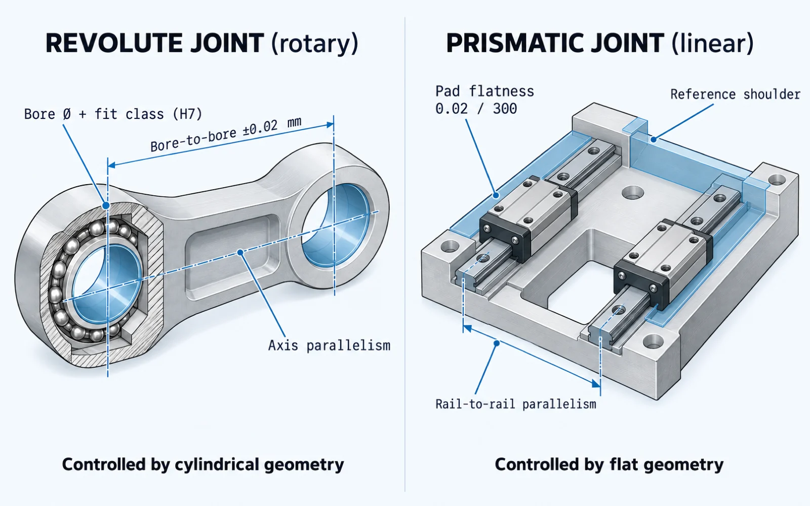
In a revolute (rotary) joint the accuracy lives in cylindrical geometry; in a prismatic (linear) joint it lives in flat geometry. They are different machining problems that happen to share an alloy.
| Revolute joint | Prismatic joint | |
|---|---|---|
| Motion | Rotation about one axis | Translation along one axis |
| Accuracy-critical features | Bearing bores, bore-to-bore distance, bore parallelism | Rail mounting faces, reference shoulder, twin-rail parallelism |
| Controlling tolerance type | Fit class (ISO 286) + position | Flatness + parallelism over length |
| Typical failure mode | Joint slop, bearing preload loss | Rail binding, uneven block preload, short bearing life |
| What kills it in aluminum | Differential thermal expansion at the bore | Surface distortion after pocketing |
| Finish strategy | Mask the bores | Mask or machine the rail faces after coating |
Searches for “prismatic joint machining” usually come from the second column, and the mistake we see most often is a print that specifies the bores beautifully and leaves the rail mounting surface at a general tolerance.
The visible parts of the same robot have the opposite problem — their drawings specify dimensions and leave the appearance as one word. See clear anodized robot face panels for that side.
Why 7075-T6 for a joint, and when is 6061 enough?
Choose 7075-T6 when the joint is strength-limited or mass-limited. Stay on 6061-T6 when it is stiffness-limited, because the two alloys have nearly the same modulus and a 7075 swap will not stop a part from flexing.
| Property | 6061-T6 (typical) | 7075-T6 (typical) | What it means for a joint |
|---|---|---|---|
| Tensile yield | 276 MPa (40 ksi) | 503 MPa (73 ksi) | 7075 lets webs and bosses run thinner at equal margin |
| Modulus of elasticity | 68.9 GPa | 71.7 GPa | ~4% apart — 7075 does not fix deflection |
| Density | 2.70 g/cm³ | 2.81 g/cm³ | 7075 is 4% heavier per unit volume; the win comes from removing volume |
| Brinell hardness | ~95 HB | ~150 HB | Better thread and bearing-seat bearing capacity |
| Residual stress risk | Lower | Higher | 7075 needs a distortion-aware routing |
| Type II dyed cosmetics | Excellent | Compromised | Visible joint covers usually stay 6061 |
The honest version of the trade: 7075 is 4% denser, so the mass saving is never in the material — it is in the geometry the extra yield strength lets you cut away. If the design will not be re-pocketed to exploit that strength, 7075 adds cost and weight at the same time.
Our 7075 robotic arm bracket is the case where it pays: the web is thinned for moving mass while the bearing bores stay at an H7 fit and ±0.02 mm position. For the full alloy comparison see 6061 vs 7075.
Why does a bearing fit that works in steel fail in aluminum?
Because aluminum expands at roughly twice the rate of bearing steel, an interference or line-to-line fit specified at 20 °C loosens as the joint warms — and a servo joint under duty cycle warms.
This is the single most under-specified item on aluminum joint drawings, so here is the arithmetic in full.
- Aluminum (7075): coefficient of thermal expansion ≈ 23 µm/m·K
- Bearing steel (through-hardened, 100Cr6 / 52100 class): ≈ 11.5–12.5 µm/m·K
- Differential: ≈ 11 µm/m·K
For a Ø50 mm bearing bore with a 40 K rise from ambient to steady-state operating temperature:
Δ = 50 mm × 11 × 10⁻⁶ /K × 40 K = 0.022 mm = 22 µmThe aluminum bore grows 22 µm more than the steel ring it holds. For reference, the entire H7 tolerance band on Ø50 is +0.025 / 0 mm — 25 µm. So a thermal swing well inside normal operation consumes almost the whole tolerance band, in the direction that releases the bearing.
What to do about it:
- Specify a fit class, not a ± value.
Ø50 H7is a complete instruction.Ø50 ±0.01is not — it says nothing about which side of nominal the tolerance must land on. - Tighten the fit for aluminum housings. Where steel practice calls for H7 on a stationary outer ring, aluminum housings commonly move to a tighter class or add a light interference, precisely to keep residual interference at temperature.
- State the temperature the dimension applies at. A drawing note reading “all dimensions at 20 °C” is standard; a joint that runs hot deserves an operating-temperature note too.
- Consider a steel or bronze sleeve where the duty cycle is severe. It costs a part and an assembly step, and it removes the problem.
- Tell us the ring’s outer diameter tolerance class. Bearing outer rings are made to ISO 492 classes; the fit you get is the combination of both parts, not the housing alone.
Rule of thumb: for an aluminum housing holding a steel bearing, budget roughly 11 µm of lost interference per 50 mm of bore diameter per 40 K of temperature rise. Check the number against your own duty cycle before you commit the print.
Prismatic joints: why the rail mounting surface is the whole job
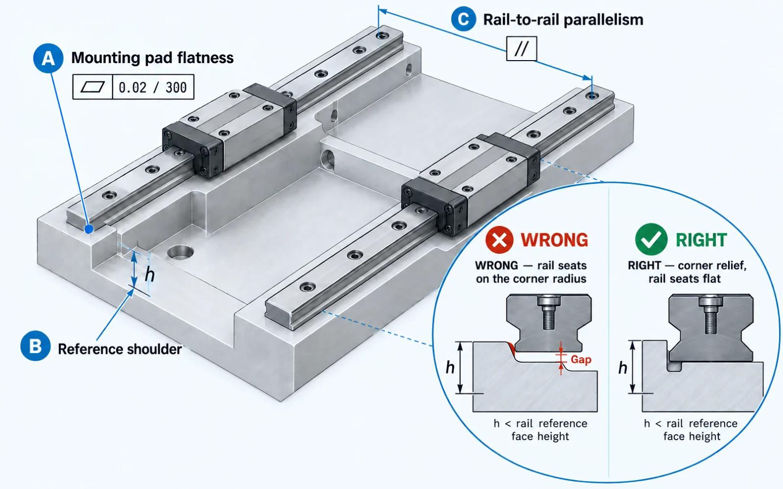
On a linear joint, the machined surface under the rail is the precision component. A profiled linear guide only delivers its rated accuracy if the surface it bolts to is within the manufacturer’s flatness and parallelism limits — the rail conforms to whatever you give it.
Four things to control, in order of how often they are missed:
1. Mounting pad flatness. A twisted or bowed pad transmits directly into the rail, which pinches the recirculating balls and either raises preload past the design value or removes it entirely. Both shorten life. A flatness callout of 0.02 mm per 300 mm is a reasonable starting point for a normal-preload guide; high-preload and high-accuracy classes are tighter. Pull the value from your specific guide series table.
2. Reference shoulder height and corner relief. Guides are installed against a machined shoulder that sets their position. The shoulder must be lower than the rail’s reference face height so the rail seats on the pad, not on the shoulder radius — manufacturers publish a maximum shoulder height and a maximum corner radius for exactly this reason. An unrelieved inside corner is the classic cause of a rail that will not sit down.
3. Twin-rail parallelism. Two rails carrying one carriage must be parallel within a permissible error that depends on preload class and block size, typically in the single-digit to low tens of microns. This tolerance is a relationship between two features, so both rail pads should be machined in the same setup. If they cannot be, say so on the print and we will fixture for it.
4. Height consistency between pads. Where two rails are on separate machined surfaces, the height difference between them twists the carriage. Treat it as a controlled dimension, not a consequence.
Aluminum adds one more consideration: pockets cut near a rail pad will move that pad. Where a prismatic joint body is lightweighted, the rail surfaces should be finished after the pocketing is complete and the stress has settled — not cut early and protected.
How much does hardcoat anodize shrink a bearing bore?
A Type III hardcoat reduces a bore diameter by approximately the full coating thickness. On a 25–50 µm coating that is 25–50 µm off the diameter, which exceeds the H7 tolerance band on most joint bores. Toleranced bores must be masked, or machined after coating.
The mechanism is specific to anodizing and catches people who are used to plating. Anodizing converts the substrate rather than adding to it, so the coating grows in both directions — roughly 50% penetration into the parent metal and 50% build-up above the original surface.
On an external cylinder, the diameter grows by about the coating thickness. On a bore, it shrinks by about the coating thickness, because the build-up on each wall moves inward by half the thickness and there are two walls on a diameter.
Worked example, Ø40 H7 bore, 50 µm Type III hardcoat:
H7 band on Ø40      = +0.025 / 0 mm   → 25 µm total
Bore reduction      ≈ 50 µm
Overrun             ≈ 2 × the entire tolerance band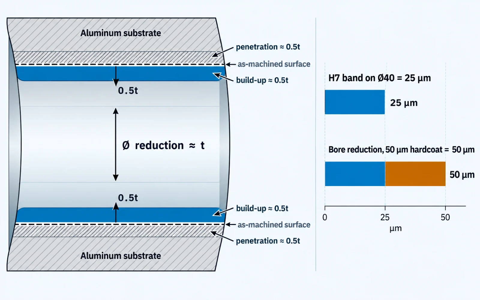
Three workable strategies, in the order we usually recommend them:
| Strategy | How it works | Cost and risk |
|---|---|---|
| Mask the bore | Bore is plugged before the tank; fit is untouched | Adds a masking operation; a small uncoated band at the mask edge |
| Machine after coating | Bore is cut undersize, coated, then finish-bored | Removes the coating at the fit; best where the bore must be coated elsewhere |
| Budget the growth | Bore cut oversize by the expected reduction | Only viable where coating thickness is tightly controlled and verified |
Whichever you choose, the drawing must say whether the dimension applies before or after coating. A bore toleranced to H7 with no coating note is ambiguous, and every shop will resolve the ambiguity differently. This is the same discipline applied on our hardcoat anodized slide plate, where the wear face carries the coating and the fits do not. Background on the finish itself is in the hardcoat anodizing guide.
How do you stop 7075 from moving while you machine it?
7075 plate and billet carry residual stress from quenching. Remove material asymmetrically and the part warps as that stress rebalances — usually after the accuracy features are already cut.
The countermeasures are routing decisions, not machine settings:
- Specify a stress-relieved temper. T651 for plate (solution treated, stretched, artificially aged) and T7351 where stress-corrosion resistance also matters. Stretch relief is done at the mill and cannot be replicated on our machines.
- Rough symmetrically. Take material from both faces in balanced passes instead of hogging one side to depth.
- Relieve between rough and finish. A pause — and for heavily pocketed joints, an intermediate stress-relief step — lets the part settle before it is measured against anything.
- Finish accuracy features last. Bearing bores, rail pads, and datum faces are cut after the bulk removal is done, in the same setup that establishes the datums.
- Leave the fixture clamping light at finish. Over-clamped aluminum machines flat and springs out of tolerance when released.
- Do not weld structural 7075. Fusion welding is generally not practicable for structural 7075. Joints are bolted, doweled, or pinned.
One more, specific to 7075-T6: it is the temper most associated with stress-corrosion cracking susceptibility under sustained tensile stress in humid or chloride environments. For an indoor industrial robot this is usually not the governing concern, but a press-fit bearing seat is a sustained tensile stress by definition. If the joint is going outdoors, into a washdown cell, or into marine service, put T73/T7351 and a coating plan on the table before release.
What goes on the drawing
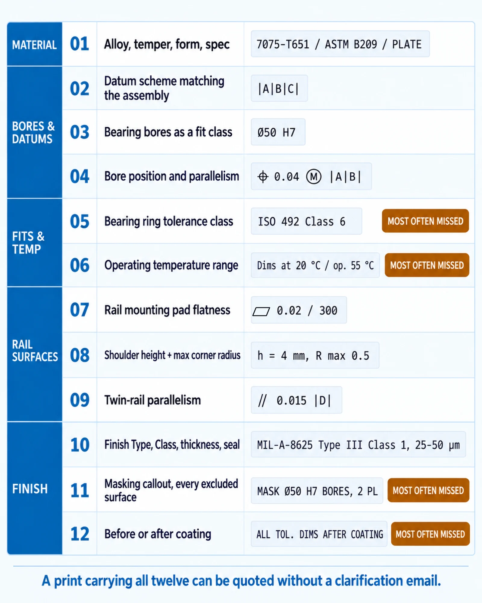
- Alloy, temper, form, and spec — e.g.
7075-T651 / ASTM B209 / PLATE - Datum scheme matching the assembly, not the machining setup
- Bearing bores as a fit class —
Ø50 H7, never a bare ± - Bore-to-bore position and parallelism as GD&T, with the datums named
- Bearing ring tolerance class the housing is mating to (ISO 492)
- Operating temperature range, if the joint runs above ambient
- Rail mounting pad flatness, with the length the tolerance applies over
- Reference shoulder height and maximum corner radius
- Twin-rail parallelism as a feature-to-feature relationship
- Finish: Type, Class, thickness, seal, color — e.g.
MIL-A-8625 Type III Class 1, 25–50 µm - Masking callout naming every surface excluded from coating
- Before or after coating stated explicitly for every toleranced feature
Items 5, 6, 11 and 12 are the four we most often have to ask for. Including them upfront typically removes a full quoting round trip. If you are assembling the wider CAD package, see how to prepare STEP and PDF drawings for CNC quotes.
Worked example: a twin-bore revolute link
A representative job, with the numbers that drove it:
| Input | Value |
|---|---|
| Material | 7075-T651 plate, 30 mm |
| Bore centers | 220 mm apart |
| Bore diameter | Ø45 H7, two places |
| Bore-to-bore position | ±0.02 mm |
| Web thickness | 6 mm, 12 mm at the bore bosses |
| Finish | Hardcoat Type III, 25–50 µm, bores masked |
| Operating rise | ~35 K above ambient |
The decisions that followed from those inputs:
- Both bores in one setup. ±0.02 mm bore-to-bore across 220 mm is not achievable by re-fixturing; it is achievable by cutting both bores without moving the part.
- Fit corrected for temperature. At Ø45 and 35 K, the aluminum-to-steel differential is about
45 × 11e-6 × 35 ≈ 17 µm— two thirds of the Ø45 H7 band. The seat was specified to retain interference hot, not at 20 °C. - Bores masked. A 50 µm hardcoat would have closed each bore by roughly 50 µm against a 25 µm band. Masking was cheaper than post-coat boring at this quantity.
- Symmetric roughing plus a relief step. 30 mm plate down to a 6 mm web is heavy removal; the stress had to settle before the bores were cut.
- Post-hardcoat gauge check. The fits were re-verified after coating to confirm the masking held, not assumed.
Sizes and volumes here are typical of this part class rather than one customer’s record.
Common mistakes
- Toleranced bores given as ± instead of a fit class. A ± says nothing about where in the band the bore must land.
- Ignoring differential thermal expansion. The fit is correct at 20 °C and gone at 60 °C.
- No before-or-after-coating note. Every shop resolves the ambiguity differently, and they will not all resolve it your way.
- Rail mounting surfaces left at general tolerance while the bores are specified to microns.
- No corner relief at the rail reference shoulder, so the rail seats on a radius.
- Switching to 7075 to fix a flexing part. The moduli differ by about 4%.
- Buying 7075 and keeping the 6061 geometry. That is a heavier, more expensive part with no benefit.
- Specifying T6 plate where T651 was meant. Stretch relief happens at the mill or not at all.
FAQ
What fit should a bearing bore have in an aluminum robot joint?
Specify a fit class from ISO 286 rather than a ± tolerance — H7 is the common starting point for a stationary outer ring. Because aluminum expands at roughly twice the rate of bearing steel, aluminum housings often need a tighter class than the equivalent steel housing to retain interference at operating temperature. State the temperature the dimension applies at.
How much does hardcoat anodize change a bore diameter?
A Type III hardcoat reduces a bore by approximately the full coating thickness, because the coating builds about half its thickness above the original surface on each of the two walls. A 50 µm coating closes a bore by roughly 50 µm — about twice the H7 tolerance band on a Ø40 bore. Mask toleranced bores, or finish-bore after coating.
Is 7075-T6 or 6061-T6 better for robot joints?
7075-T6 is better when the joint is strength-limited or mass-limited, because its roughly 1.8× higher yield strength lets webs and bosses be cut thinner. 6061-T6 is sufficient when the joint is stiffness-limited, since the two alloys’ moduli differ by about 4% and 7075 will not reduce deflection. 7075 is also 4% denser, so the weight saving comes from removing material, not from the alloy itself.
What tolerance do linear rail mounting surfaces need on a prismatic joint?
Take the value from the guide manufacturer’s series table, because it depends on preload class and block size. A flatness of 0.02 mm per 300 mm is a reasonable starting point for a normal-preload profiled guide, with twin-rail parallelism typically in the single-digit to low tens of microns. Machine both rail pads in one setup wherever the parallelism is tight.
Why does a 7075 joint warp after machining?
7075 retains residual stress from quenching, which rebalances as material is removed and distorts the part. Specify a stress-relieved temper such as T651 or T7351, rough symmetrically from both faces, allow a relief step before finishing, and cut bearing bores and rail pads last in the setup that establishes the datums.
Can a robotic joint be welded in 7075?
Generally no. Fusion welding is not practicable for structural 7075, so joints are bolted, doweled, or pinned. Where a welded design is required, 6061 is the far more practicable alloy and the joint should be re-analyzed for the lower yield strength.
Conclusion
The alloy is the easy decision. A 7075-T6 robot joint succeeds or fails on four details that sit outside the material callout: a bearing fit expressed as a class and corrected for aluminum’s thermal expansion, rail mounting surfaces controlled as precision features in their own right, a hardcoat plan that keeps 25–50 µm of coating out of a 25 µm tolerance band, and a routing that respects residual stress.
Put those on the print and the joint holds its repeatability through the duty cycle. Leave them off and the tolerance stack gets resolved by whoever machines it — which is a decision you did not make.
Send the joint drawing and we will return a fit, datum, and coating review before the quote locks in an ambiguity.