
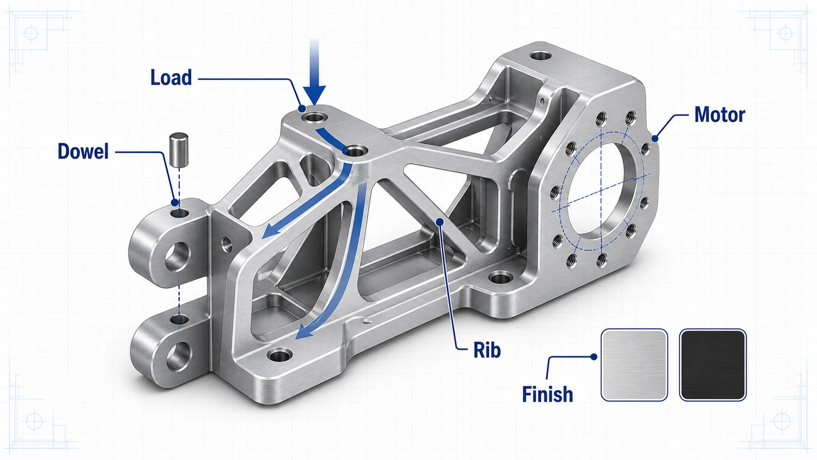
Robotics brackets are not ordinary mounting plates. They affect payload, stiffness, repeatability, vibration, cable routing, service access, and sometimes safety. A CNC machined aluminum bracket may locate a servo motor, carry an end effector, hold a sensor, or connect moving links. Small errors can become large positioning problems at the tool center point.
The best robotics bracket designs balance weight reduction with stiffness and machinability. Aluminum is a strong fit, but alloy, geometry, tolerances, and finishing should be selected around the robot function.
Typical robotics bracket requirements
| Requirement | Design implication |
|---|---|
| Low weight | Use pockets, ribs, and high-strength alloys where justified |
| High stiffness | Keep load paths direct and avoid thin unsupported sections |
| Repeatable alignment | Use dowel holes, datums, and controlled mounting faces |
| Serviceability | Use inserts or robust thread engagement for repeated assembly |
| Corrosion and wear resistance | Specify anodize or hardcoat where needed |
| Cable and sensor access | Add generous routing features without weakening the bracket |
A bracket that is easy to machine but flexible may hurt robot performance. A bracket that is extremely light but expensive to inspect may not be right for production.
Alloy selection: 6061 or 7075
6061-T6 is a good default for many robotics brackets. It machines well, anodizes consistently, and is cost-effective. Use it for sensor brackets, light-duty mounts, frame plates, covers, and moderate-load structures.
7075-T6 is worth reviewing when the bracket is highly loaded, weight-sensitive, or compact. It can reduce mass while maintaining strength. This is useful for end-of-arm tooling, moving links, actuator brackets, and compact motor mounts. The tradeoff is higher material cost and more attention to corrosion protection and finish.
If the part is a flat fixture-like robot base plate, MIC-6 may be useful for stability. For structural brackets, 6061 or 7075 is usually more appropriate.
Design for stiffness, not just strength
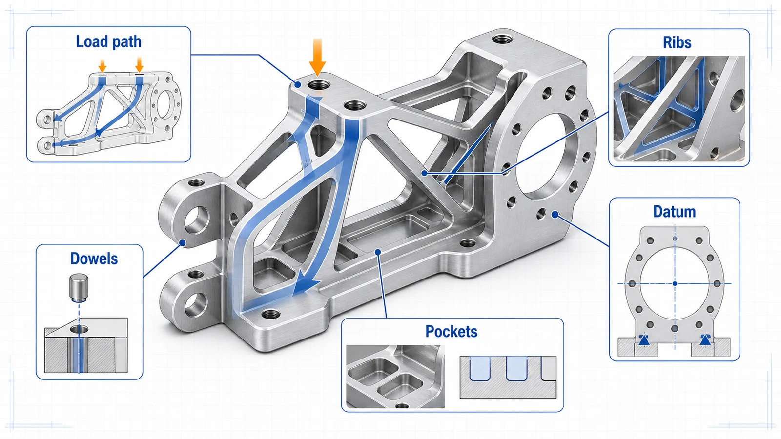
Robotics parts often fail the performance target by deflecting, not by breaking. A bracket can have enough strength but still allow vibration or positioning error. Stiffness comes from geometry: section height, rib placement, load path, mounting span, and wall thickness.
Use ribs along load paths rather than decorative pockets. Avoid removing material around motor faces, bearing supports, and dowel locations. Keep mounting faces broad enough to resist twisting. If pockets are used for weight reduction, leave continuous material around the features that control alignment.
Hole patterns, dowels, and datums
Bolts clamp. Dowels locate. If a robotics bracket must be repeatable after service, add dowel holes or precision locating features. Use position tolerances tied to functional datums instead of loose chain dimensions.
Motor mounts, gearbox interfaces, linear rail mounts, and sensor brackets should define the datum face and key hole pattern. If the robot assembly uses off-the-shelf components, include the mating interface standard or model in the RFQ notes.
Threads and inserts
Tapped aluminum holes work for many brackets, but repeated service can wear threads. For brackets that will be assembled often, use helical inserts or other threaded inserts. For high-load joints, review thread engagement length and bolt preload.
If the bracket will be anodized, decide whether threads are masked, tapped after anodize, or allowed to coat. Hardcoat in threads can create assembly issues if not planned.
Machining process: 3-axis or 5-axis
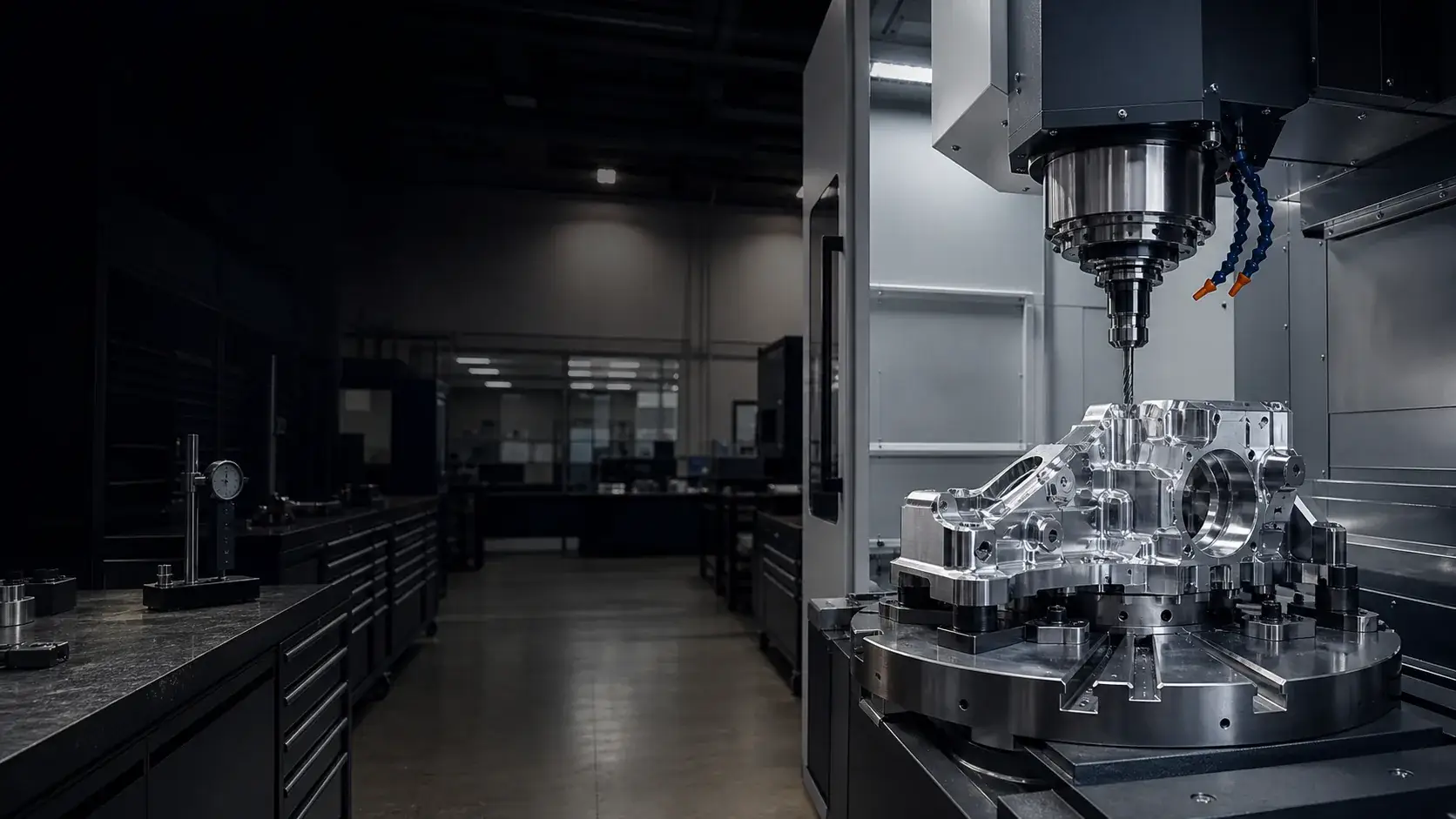
Many brackets can be machined efficiently on 3-axis equipment using two or three setups. 5-axis machining may help when angled faces, compound surfaces, or multiple critical interfaces need to be controlled in fewer setups. The process decision should be based on total cost and tolerance risk, not machine prestige.
Review the 3-axis vs 5-axis aluminum machining guide if the bracket has features on many sides.
Finish choices
Clear anodize is common for industrial robotics parts. Black anodize is useful for machine vision, optics, and customer-facing hardware. Hardcoat anodize may be used on wear surfaces, sliding contact areas, or frequently handled tooling.
For moving assemblies, also consider surface roughness and edge breaks. Sharp edges catch cables, cut gloves, and damage nearby components. Controlled deburring is part of the design.
RFQ package
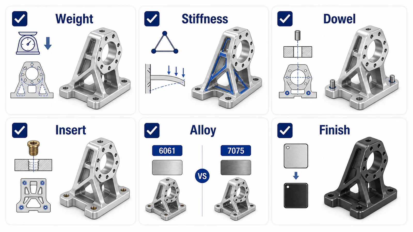
Send STEP, PDF drawing, alloy, finish, quantity, critical hole patterns, datum scheme, insert requirements, and application notes. Mention whether the bracket is static, moving, payload-sensitive, safety-related, or cosmetic.
Robotics brackets reward clear engineering intent. Show the load path and alignment requirements, and the machining plan can protect both performance and cost.