
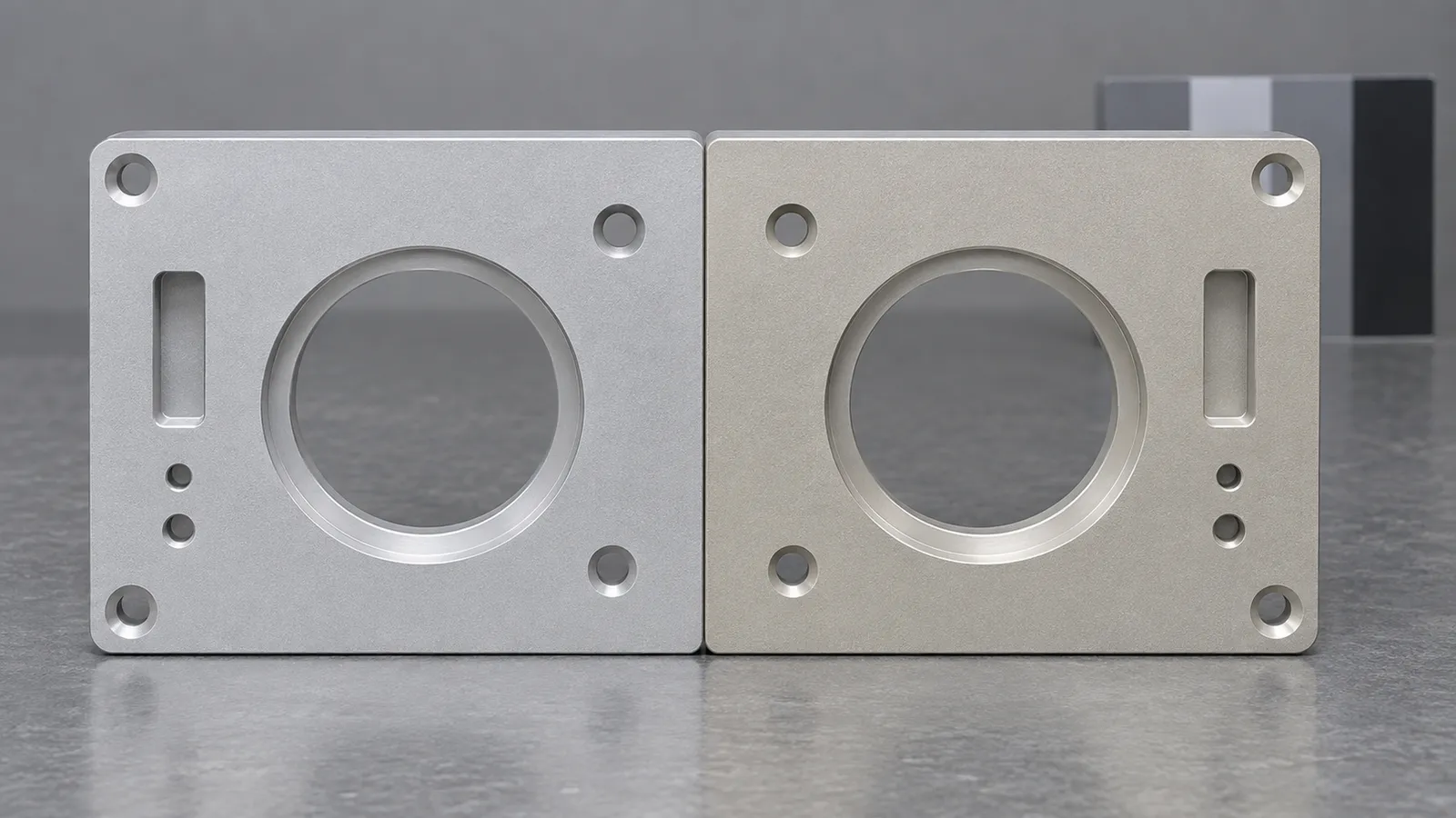
Direct answer: Clear anodize — Type II Class 1, undyed — is a transparent oxide film. It adds durability and corrosion resistance, and it adds no color of its own. What you see on the finished part is the aluminum underneath: the finishing passes, the grain, the alloy, and any handling marks, all sealed in permanently. That makes three things drawing requirements rather than shop decisions: the pre-anodize texture, the film thickness range, and the location of rack contact marks. If parts have to match each other, they also have to be one alloy, ideally one plate lot, processed as a set.
Specification summary
| Parameter | Typical for clear anodized CNC parts | Reference |
|---|---|---|
| Finish | Type II Class 1 (undyed), sealed | MIL-A-8625 |
| Film thickness | 5–15 µm cosmetic; 15–25 µm where corrosion drives it | MIL-A-8625 Type II |
| Dimensional growth | About half the film thickness per surface | — |
| Pre-anodize texture | Bead blast to a stated grit, or a stated Ra | ISO 4287 |
| Alloy for cosmetic work | 6061 | ASTM B209 |
| Rack contact | Location named on the drawing | — |
| Color expectation | Consistent within one alloy and lot; drifts across lots | — |
“Clear” is not a color
Nothing in the clear anodize process makes the part silver. The part was already silver; the film is transparent and lets it show.
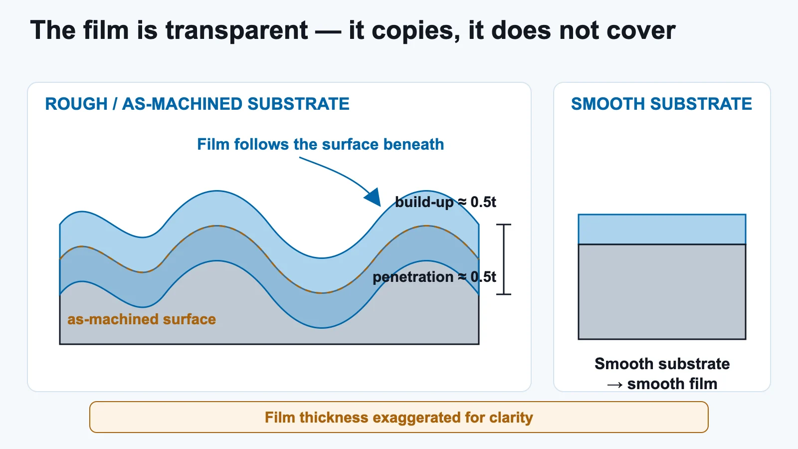
That sounds obvious and it is the source of most clear anodize disagreements, because it inverts how people reason about finishes. With a dyed finish, the coating determines the look and the substrate is mostly hidden. With clear, the coating determines almost nothing about the look and the substrate determines all of it.
What comes through the film:
- Toolpath witness lines between adjacent passes, even when the dimensional step is negligible.
- Cut direction. Two faces finished in different directions read as different shades at the same viewing angle.
- Rolling grain in plate, especially after a light finishing cut.
- Alloy. 6061 gives neutral silver. 7075 reads yellower. Copper-bearing 2024 reads darker and less even. High-silicon castings go gray.
- Any handling mark made after the final machining operation, which the film then makes permanent.
The working rule: on clear anodize, surface preparation is the appearance. Anodizing only fixes it in place.
Surface preparation is the specification
Choosing the pre-anodize texture is the main appearance decision on a clear anodized part, and it is a decision the drawing should make rather than the shop.
| Pre-anodize texture | Finished appearance | Typical use |
|---|---|---|
| As-machined | Directional, tool marks visible, slight sheen | Internal parts, or a deliberate machined look |
| Bead blast, fine grit | Uniform soft matte | Most cosmetic clear parts |
| Bead blast, coarse grit | Deeper matte, visible texture | Where machining must be fully hidden |
| Grained / brushed | Directional satin; direction is a requirement | Consumer-facing panels and trim |
Two notes worth putting on the drawing:
- Blasting hides toolpaths; it does not hide geometry. A step, a mismatch between setups, or a chatter pattern will still be visible after blasting and anodizing.
- Blast media leaves its own signature. Changing media or grit between batches changes the appearance even when everything else is identical, so state the grit or an Ra range if batches must match.
For how to write the roughness call itself, see surface roughness options.
Film thickness: dimensions and corrosion, not color
On a clear film, thickness has much less effect on appearance than it does on a dyed one — but it still drives dimensions and corrosion resistance, so it belongs on the drawing as a range.
- Growth. The film builds about half its thickness outward on each surface. A 10 µm film adds roughly 5 µm per face, grows an external dimension by roughly 10 µm, and closes a hole by roughly 10 µm on diameter.
- Where that matters. Press fits, dowel holes, bearing seats, close slots, and any thread whose class of fit is stated. It rarely matters on flat cosmetic faces.
- Corrosion. Thicker films resist more, which is why non-cosmetic clear work often runs thicker than cosmetic work.
- Edges. Sharp outside corners build film differently from flat faces and can be thin or brittle. A small edge break is worth specifying on parts that will be handled.
Say explicitly whether toleranced dimensions apply before or after coating. On a part with fits, this single line prevents most post-finish rework — the same discipline described for thicker films in the hardcoat guide.
Rack marks are part of the process
Anodizing requires an electrical connection to the part, so wherever the rack grips it there is an uncoated or differently-coated spot. This is inherent, not a defect. The only negotiable thing is where it lands.
Because clear anodize hides nothing, a rack mark on a visible face is obvious. Handle it on the drawing:
- Name a permitted contact zone — a back-face boss, a non-visible edge, or inside a hole that hardware later covers.
- State the exclusion —
NO RACK CONTACT MARKS ON SURFACE A. - Accept the trade-off on small parts. Very small or fully cosmetic parts may need a secondary operation or a different holding scheme, which costs money; deciding this at quote time is cheaper than at first article.
What “color match” can and cannot mean
Two clear anodized parts match when the aluminum under them matches. They drift when the alloy, the plate lot, or the surface preparation drifts — none of which the anodizing line controls.
Realistic expectations:
| Situation | Expect |
|---|---|
| Same alloy, same plate lot, same prep, same rack | Good match |
| Same alloy, different plate lot | Slight drift; usually acceptable |
| Different alloys (6061 and 7075) | Visible mismatch; will not resolve |
| Same drawing, different blast grit | Visible mismatch in texture and apparent shade |
| Parts made months apart | Drift proportional to how much of the above changed |
If an assembly’s visible parts must match, say so as a requirement: specify one alloy for all visible parts, state that they are a matched set, and allow them to be processed together. That instruction costs almost nothing at the quoting stage and is close to impossible to retrofit.
Acceptance criteria that can actually be inspected
Replace “cosmetic finish” with conditions. A finish requirement that does not state how the part is looked at cannot be failed or passed consistently.
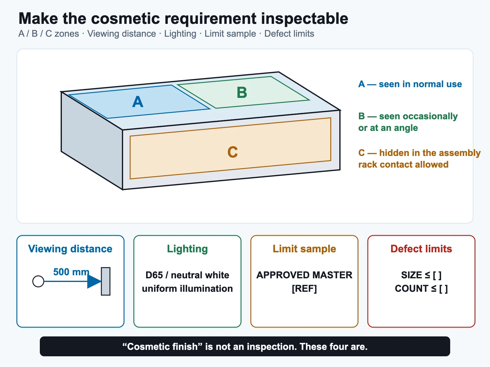
The four elements:
- Zoned surfaces. A (seen in use), B (seen occasionally), C (hidden). Different limits on each; rack contact allowed in C.
- Viewing distance. A part judged at 300 mm and the same part at arm’s length are different parts.
- Lighting. Diffuse office light and a bright inspection lamp reveal different things.
- Limit sample on recurring work — a physical part defining the acceptable extremes, agreed by both sides.
Written defect limits (maximum size and count of marks per zone) are worth adding where volume justifies them, but the sample is what settles arguments about texture and shade, which numbers describe poorly.
What goes on the drawing
- Alloy, temper, form and spec — one alloy across all visible parts
- Finish:
MIL-A-8625 TYPE II CLASS 1, 5–15 µm, SEALED - Pre-anodize texture: blast grit or Ra range, direction if grained
- Cosmetic zones marked on the views
- Viewing distance and lighting for acceptance
- Limit sample reference, on recurring work
- Rack contact zone, named, with the exclusion stated
- Masking list — grounding pads, fits, sealing faces
- Before or after coating, for every toleranced feature
- Matched set, if parts must match each other
- Edge break, on handled parts
- Handling and packing note — the finish is final when it leaves the tank
Common mistakes
- Assuming clear anodize evens out the machining. It magnifies it, because there is no dye to absorb variation.
- No pre-anodize texture on the drawing. The texture is the appearance.
- Expecting match across alloys. 6061 and 7075 will not match under a clear film.
- Cosmetic requirements with no viewing conditions. Unrepeatable by construction.
- No rack contact zone, so the mark appears on the visible face.
- Film thickness treated as cosmetic-only and left off, then fits close up.
- Grounding pads unmasked on an insulating finish.
- Parts from different months expected to match with no matched-set instruction.
FAQ
What is clear anodizing?
Type II Class 1 anodizing: an undyed, transparent anodic oxide film grown on the aluminum, then sealed. It improves corrosion and wear resistance and gives a durable surface, and it adds no color of its own — the silver appearance is the aluminum showing through the film.
Why do clear anodized parts show machining marks?
Because there is no dye to hide them. A clear film is transparent, so toolpath witness lines, cut direction and grain all remain visible and become permanent once the film is sealed. If the machined look is not wanted, specify a pre-anodize texture such as bead blasting to a stated grit.
How much does clear anodize add to a dimension?
Roughly half the film thickness on each surface. A 10 µm film adds about 5 µm per face, grows an outside dimension by about 10 µm and closes a hole by about 10 µm on diameter. State whether toleranced dimensions apply before or after coating, and mask fits that cannot absorb the growth.
Will clear anodized parts from different batches match?
They match as well as the aluminum under them matches. Same alloy, same plate lot and same surface preparation gives a good match; different alloys will not match at all. If visible parts must match, specify one alloy, call them a matched set, and allow them to be processed together.
Can rack marks be avoided on anodized parts?
Not eliminated — anodizing needs electrical contact, so an uncoated contact point always exists somewhere. It can be placed: name a permitted contact zone on a hidden face, edge or fastener hole, and state that no contact marks are allowed on visible surfaces.
Is clear or black anodize better for a cosmetic part?
Black hides substrate variation and gives the highest contrast for laser-marked legends. Clear shows the machined surface, which suits a deliberately machined look and is cheaper to keep consistent when the underlying material is controlled. The clear versus black comparison covers the choice; for how to keep black consistent, see the matte black appearance guide.
Conclusion
Clear anodize is the most honest finish aluminum has. It protects the part and hides nothing about how it was made, which makes it cheap to specify well and expensive to specify vaguely.
Decide the texture, give the film a thickness range, put the rack marks somewhere you chose, and say whether the parts have to match each other. Send the drawing and we will return that review before the first batch sets an expectation nobody wrote down.