
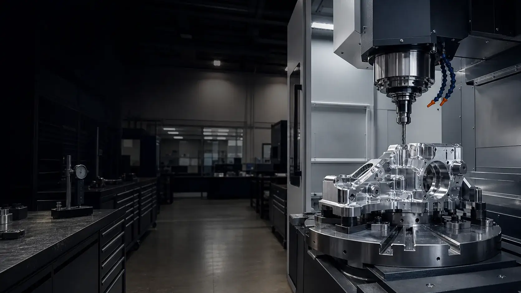
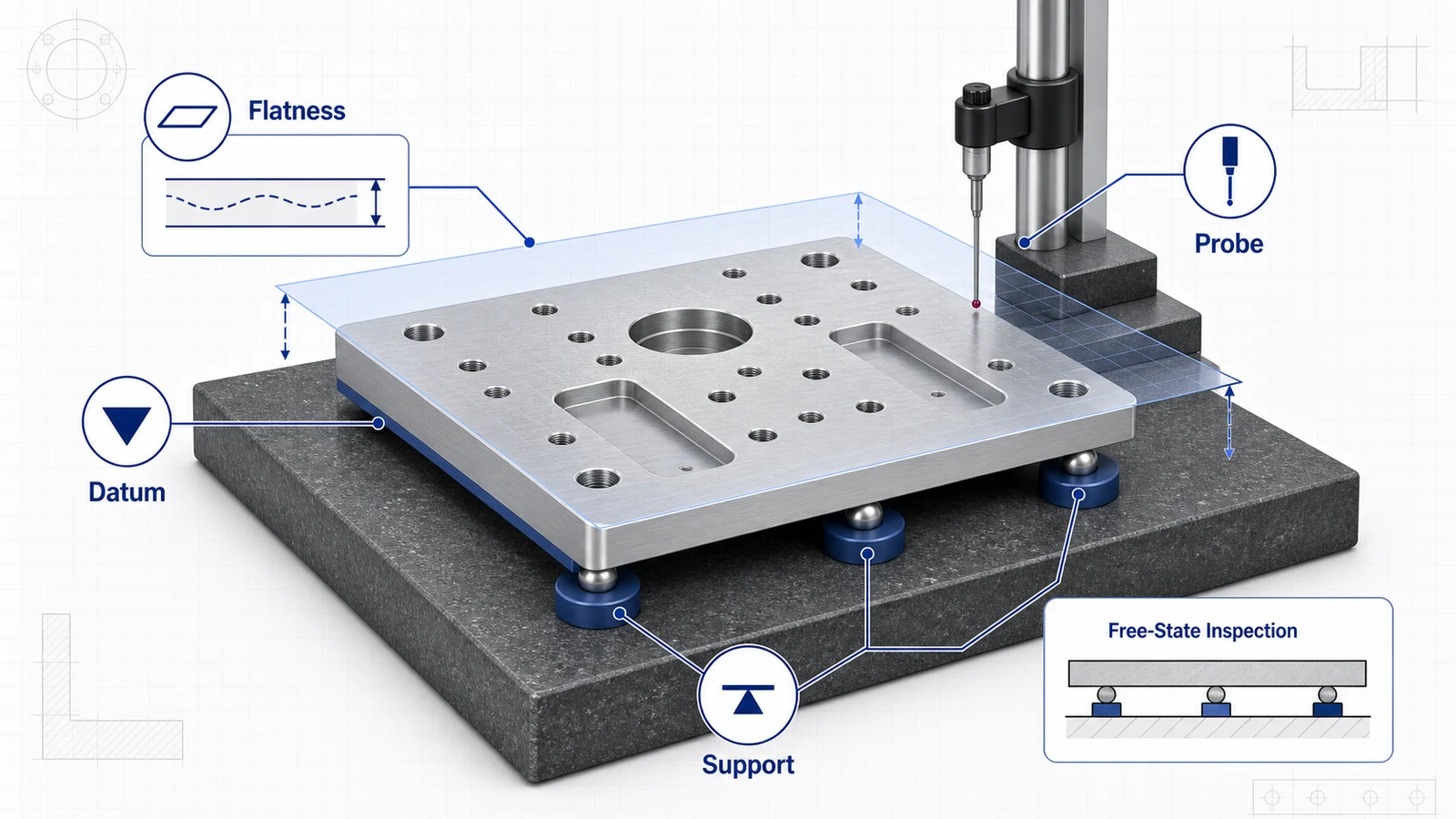
Flatness problems in aluminum CNC machining usually appear after the part leaves the vise, after one side is heavily pocketed, or after finishing removes balanced material. The part may measure correctly while clamped, then bow when released. This is common with plates, housings, thin covers, fixture bases, and large brackets.
Flatness is not only a machining issue. It is a design, material, workholding, roughing, finishing, and inspection issue. If the drawing simply says “flat” without defining how flat, where, and under what condition, the quote will be uncertain.
Why aluminum parts move
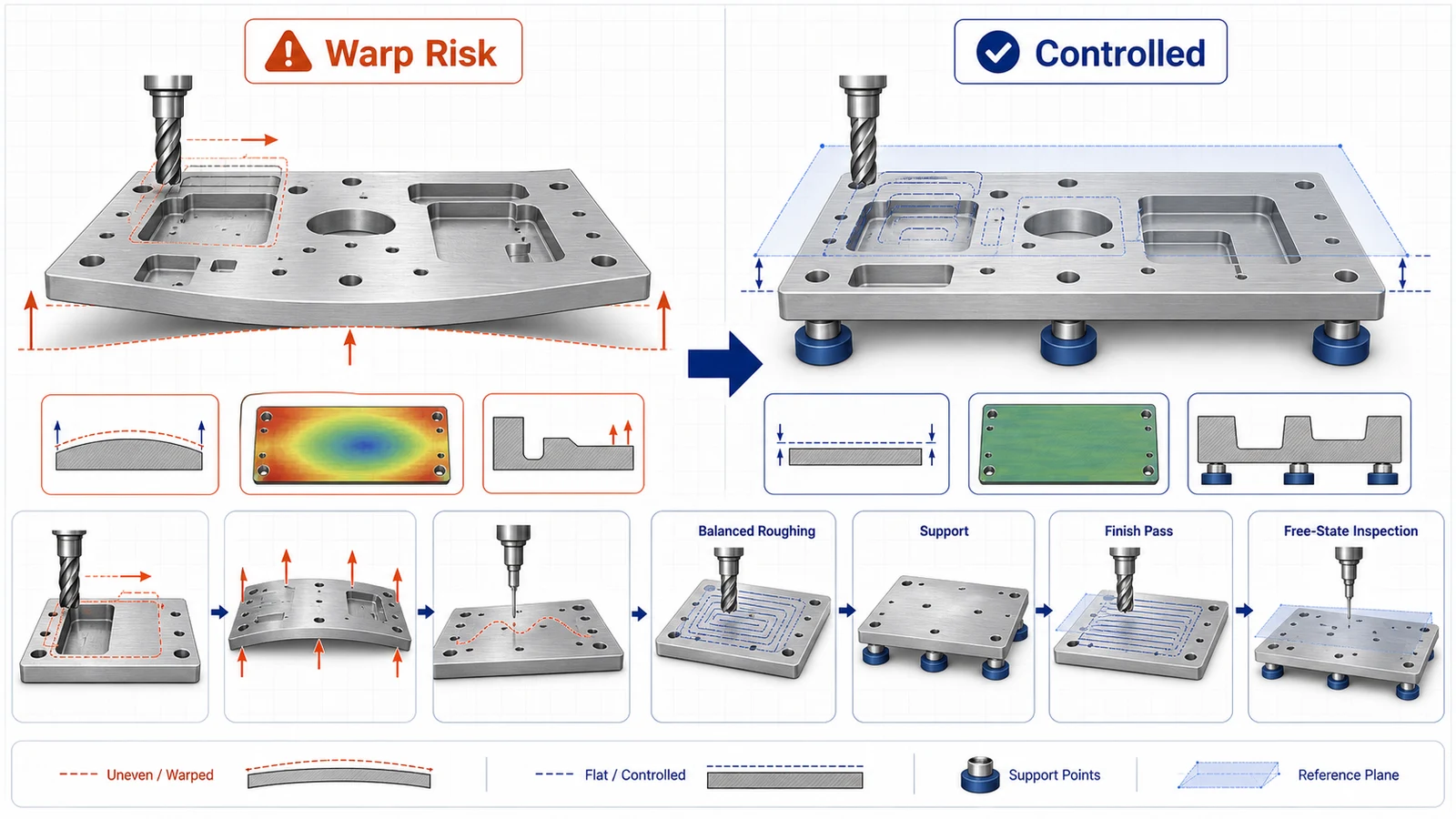
Aluminum stock can contain internal stress from rolling, extrusion, heat treatment, or prior processing. When machining removes material, that stress can redistribute. Thin sections move more because they have less stiffness. Asymmetric material removal makes the issue worse.
Workholding can also hide flatness problems. A plate clamped hard against a fixture may look flat during machining. Once unclamped, it may relax. This is why free-state inspection matters for parts that are not bolted flat in use.
Material selection for flat parts
| Material | Flatness behavior | Best use |
|---|---|---|
| 6061-T6 plate | Good general choice, but can move after heavy pocketing | Structural plates, brackets, housings |
| 7075-T6 plate | Strong but still stress-sensitive in thin designs | High-strength lightweight plates and arms |
| MIC-6 tooling plate | Excellent stability for plate work | Fixture plates, inspection bases, tooling |
| 5052 | Useful for softer sheet-like parts | Formed or lightly machined components |
MIC-6 is often the best starting point when flatness is the main requirement. For loaded parts, 6061 or 7075 may still be required, with a machining plan built around movement control.
Design rules that help flatness
Keep thickness as uniform as possible. Avoid removing a deep pocket from only one side of a thin plate unless the part has enough remaining stiffness. Add ribs instead of leaving wide unsupported floors. Use generous internal radii so finishing tools can cut smoothly without chatter.
If the part must be lightweight, discuss whether roughing both sides can balance stress. Sometimes machining shallow pockets on both sides produces a flatter part than one aggressive pocket on one side.
For large covers and housings, consider whether the part is measured free state or assembled state. A cover that seals when bolted to a rigid base may not need the same free-state flatness as a precision fixture plate.
Machining strategy
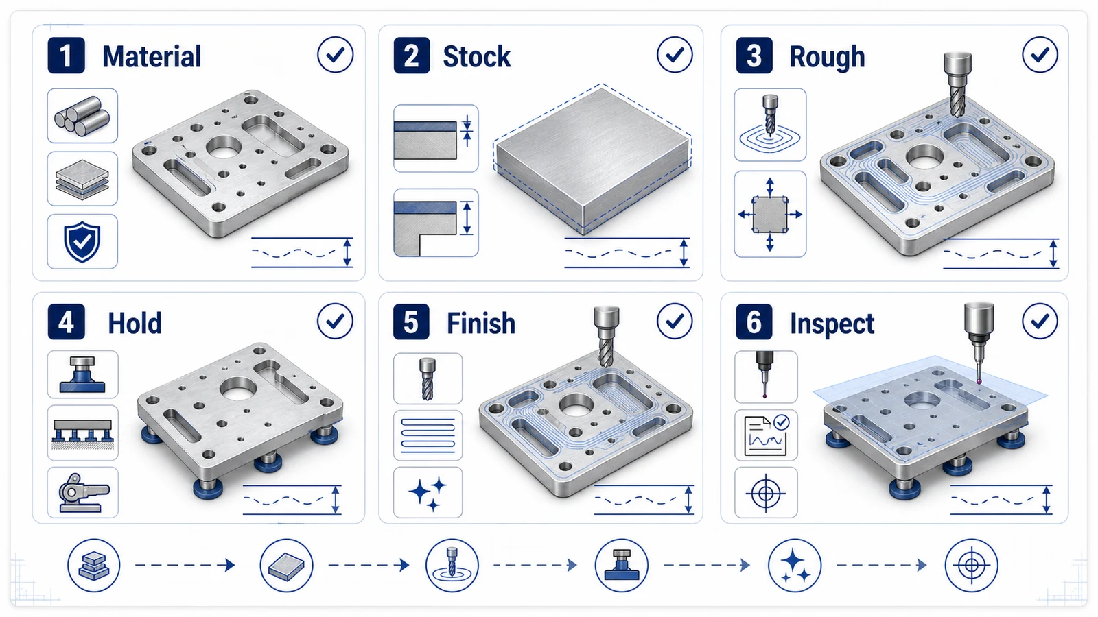
A flatness-focused machining process may include:
- Oversized stock with enough cleanup allowance.
- Roughing operations that remove material gradually.
- Flipping the part to balance material removal.
- Resting the part between roughing and finishing when needed.
- Light finishing passes after stress movement has occurred.
- Dedicated soft jaws, vacuum fixtures, or support tooling.
This adds time, but it is often cheaper than machining a part quickly and rejecting it at final inspection.
Workholding concerns
Clamping pressure can distort aluminum. Thin plates, covers, and wide housings are especially vulnerable. If the part is pulled flat during machining, it may spring back later. Vacuum fixtures, adhesive workholding, custom nests, or controlled clamp locations may be needed for sensitive parts.
Designers can help by leaving temporary tabs, adding fixture-friendly stock, or allowing machining pads that are removed later. If those options are acceptable, discuss them during RFQ.
How to specify flatness on a drawing
A useful flatness note identifies the face, value, and inspection condition. For example: “Datum A flatness 0.05 mm, inspected free state after finish.” If the part should be inspected while bolted to a reference plate, say that instead.
Do not rely on thickness tolerance. Thickness controls distance between faces, not whether one face is flat. Also avoid applying tight flatness to every surface unless every surface truly needs it.
Finishing effects
Anodizing, bead blasting, and heat exposure can affect thin aluminum parts. The finish itself may not be the main cause of movement, but handling, racking, and process steps add risk. If flatness and cosmetic anodize are both important, the supplier should know before quoting.
For hardcoat or Type II anodize, specify whether flatness applies before or after finish. If a surface is masked, show it clearly.
Inspection method
Flatness can be measured on a surface plate, CMM, height gauge, or dedicated fixture. Large thin parts need support points defined carefully. If the inspector presses the part flat by hand, the result is meaningless. If the part rocks on burrs, the result is also misleading.
For production, define how flatness is checked and how often. A first article report may include detailed flatness data, while later batches use sampling.
Flatness control starts in design. Choose the right alloy, leave enough stiffness, define the real requirement, and let the supplier plan workholding and roughing around it.