
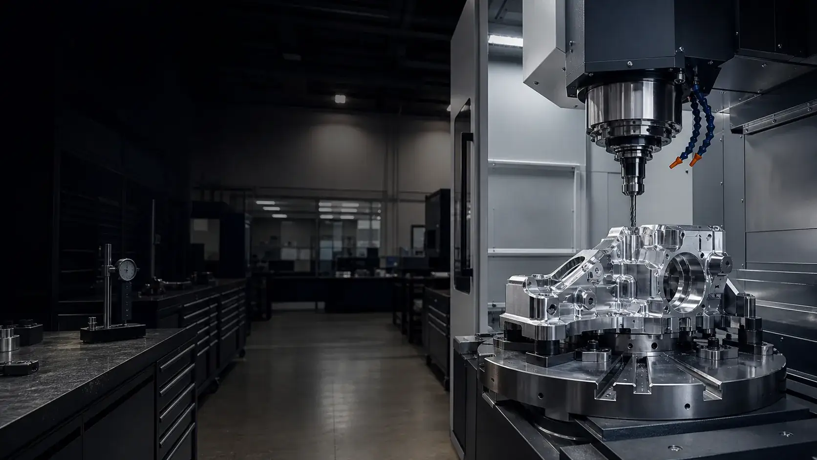
Most aluminum CNC drawing mistakes are not dramatic. They are small missing details that force the supplier to ask questions or make conservative assumptions. The result is a slower quote, higher price, or a part that technically matches the model but does not work as intended.
A good drawing does not need to dimension every surface. It needs to communicate material, function, tolerances, finish, threads, inspection, and revision control clearly.
Mistake 1: Calling out only “aluminum”
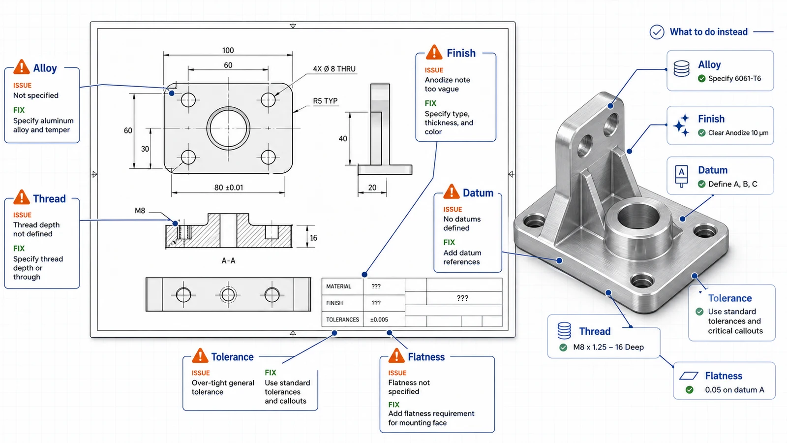
“Aluminum” is not a material specification. 6061-T6, 7075-T6, 5052-H32, 2024-T351, and MIC-6 behave differently. They vary in strength, machinability, corrosion resistance, anodizing appearance, stability, and cost.
If the alloy is flexible, say so with approved alternates. If the alloy is critical, include material certificate requirements. For most general machined parts, 6061-T6 is a reasonable default. For high-strength lightweight parts, review 7075. For flat fixture plates, review MIC-6.
Mistake 2: Over-tight title-block tolerances
A tight general tolerance can make the entire part expensive. If every dimension falls under +/-0.02 mm, the supplier may need to machine and inspect many non-functional features as if they were precision fits.
Use general tolerances for ordinary features and specific tolerances for critical features. Tighten the bore, dowel pattern, sealing face, or mounting relationship that matters. Leave clearance pockets and non-critical profiles reasonable.
Mistake 3: Missing datums
Datums define how the part is located for manufacturing and inspection. Without datums, hole position, flatness, perpendicularity, and profile tolerances are open to interpretation.
Choose datums based on function. A mounting face, precision bore, or locating edge may be the right primary reference. A cosmetic outside edge usually is not. For multi-face parts, datums help the supplier decide whether setup strategy or 5-axis machining is needed.
Mistake 4: Vague anodize notes
“Anodize black” or “clear finish” is not enough for a production drawing. Anodize type, color, thickness, sealing, masking, and dimensional condition may all matter.
A better note might include Type II or Type III, color, thickness range, dimensions after finish, and masked areas. If cosmetic appearance matters, identify visible faces and rack mark locations. If conductivity matters, specify masked grounding lands.
Use the anodized aluminum design checklist to build the note.
Mistake 5: Incomplete thread callouts
Thread callouts should include size, pitch, class or fit where applicable, depth, and whether the hole is blind or through. If inserts are required, specify the insert standard and installation requirement.
For aluminum, thread engagement and repeated assembly matter. A tapped 6061 hole may be fine for one-time assembly. A service cover may need inserts. If the part will be anodized, decide what happens to the threads.
Mistake 6: Confusing thickness tolerance with flatness
A plate can meet thickness tolerance and still be warped. If a face must seal, mount, or locate another component, specify flatness. Also define whether it is inspected free state or bolted condition.
Large thin aluminum parts need careful workholding and roughing. If flatness is critical, tell the supplier before quoting.
Mistake 7: No surface roughness where it matters
Many machined surfaces do not need a special roughness callout. But sealing faces, sliding surfaces, thermal interfaces, and cosmetic faces may. A generic roughness requirement on all surfaces can add cost. No roughness requirement on a sealing face can create function risk.
Specify roughness selectively.
Mistake 8: Model and drawing mismatch
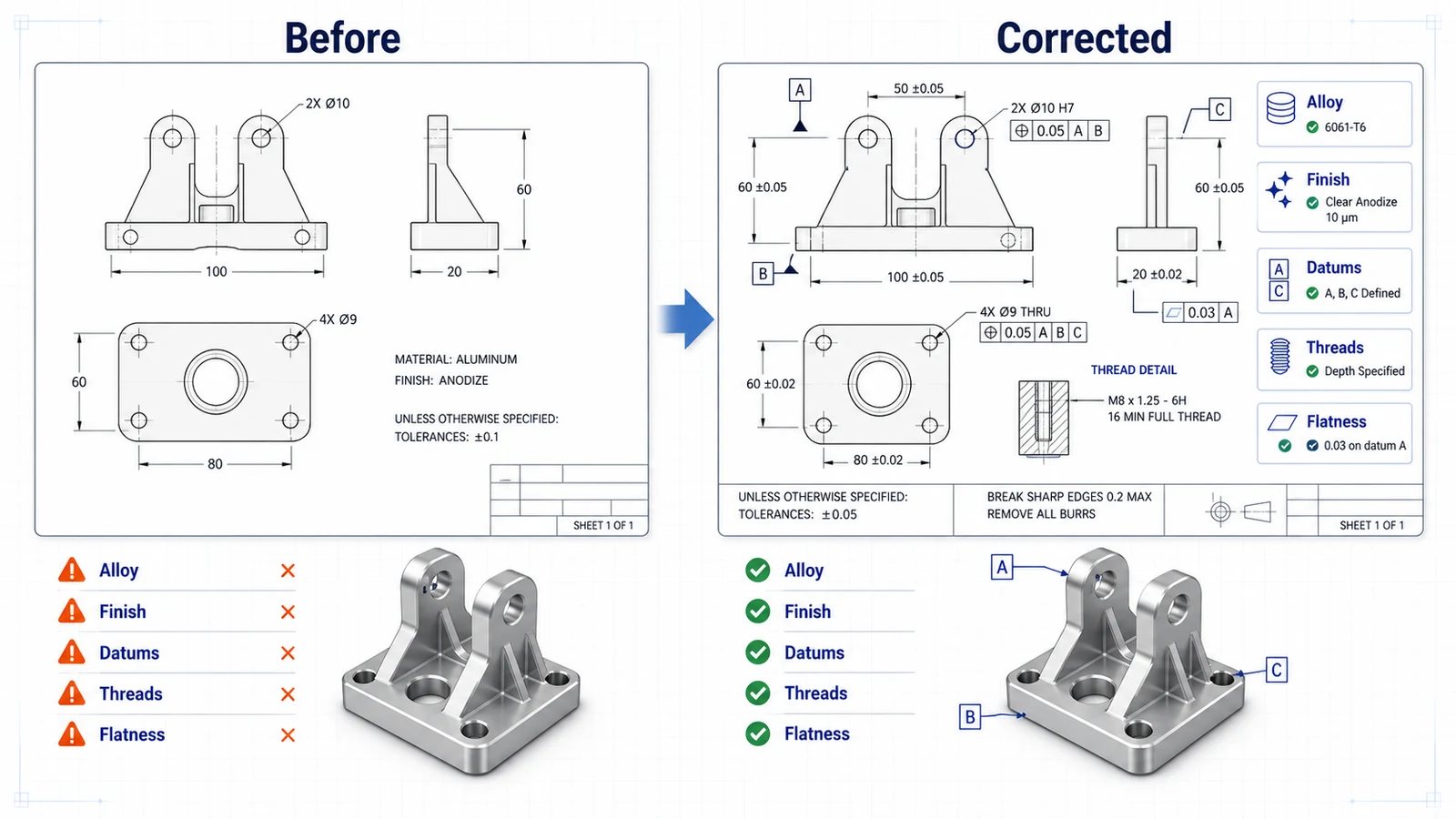
If the STEP model and PDF drawing disagree, the quote stops. Common issues include missing chamfers, old hole sizes, different revision letters, or suppressed features in the exported model.
Before sending an RFQ, open the STEP file in a neutral viewer and compare it with the PDF. Make sure file names include the same revision.
Mistake 9: Missing inspection requirements
If you need FAI, CMM report, material certificates, finish certificates, or leak testing, include that in the RFQ. Inspection and documentation affect cost and lead time.
This is especially important for OEM buyers who need repeat production. A prototype may only need a few verified dimensions, while a production release may need material traceability, finish certification, and a first article report tied to the drawing revision. Put those expectations in the quote request so they are planned as part of manufacturing, not added after parts are complete.
Simple pre-send review
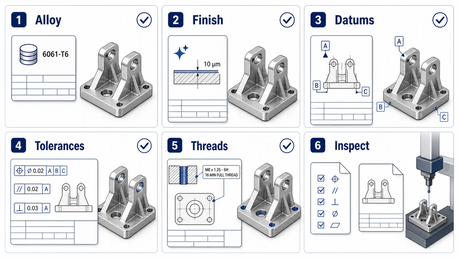
Before submitting aluminum CNC drawings, confirm alloy, finish, critical tolerances, datums, threads, flatness, surface roughness, quantity, inspection, and revision. That review can save days of back-and-forth and prevent expensive assumptions from entering the quote.