
Threads are small features with large consequences. A CNC machined aluminum part may fail in assembly because a tapped hole is too shallow, too close to an edge, poorly specified, coated with anodize, or not strong enough for repeated service. Good thread callouts prevent quote delays and assembly problems.
Aluminum taps well, especially 6061, but it is softer than steel. Thread engagement, insert choice, finish condition, and inspection should match the load and service life of the part.
What every thread callout should include
At minimum, specify:
- Thread size and pitch, such as M4 x 0.7 or 1/4-20 UNC.
- Thread depth, not only drill depth.
- Whether the hole is blind or through.
- Thread class or fit where required.
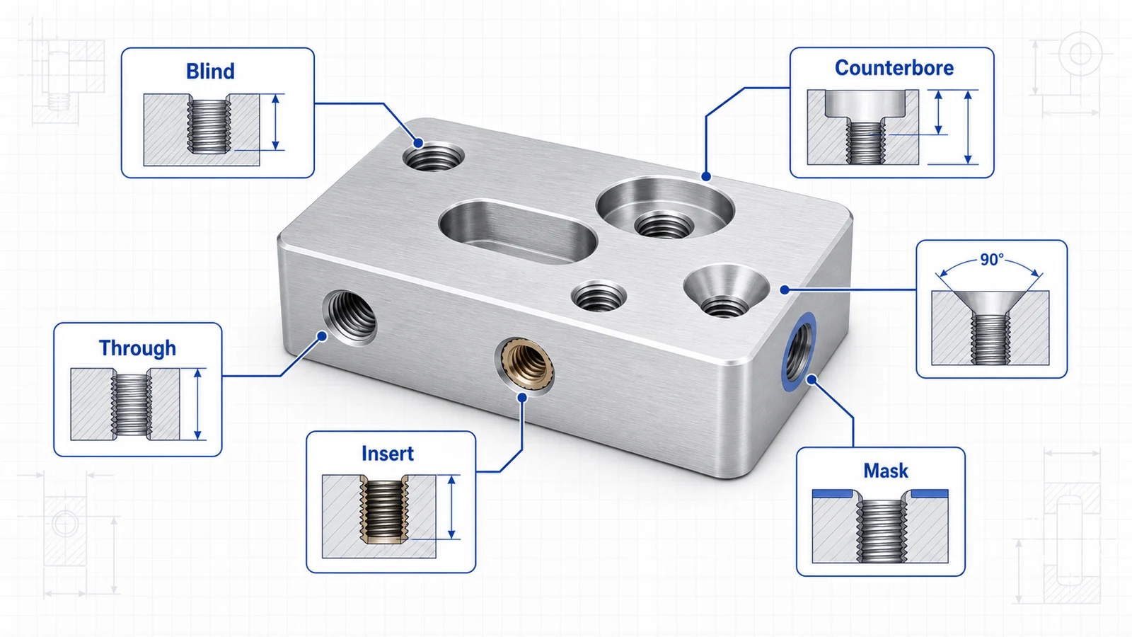
- Counterbore, countersink, or spotface details.
- Insert type if used.
- Finish condition, such as masked, tapped after anodize, or dimensions after finish.
The model may show a hole, but the drawing must define the thread.
Thread depth vs drill depth
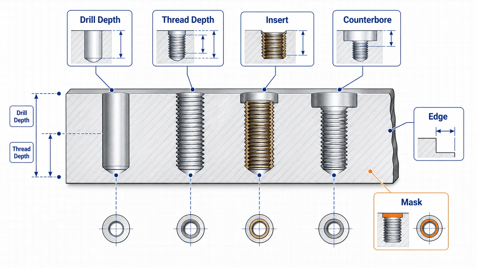
Blind tapped holes need enough drill depth beyond the required thread depth. A tap cannot cut full threads to the very bottom of a blind hole. If the drawing specifies thread depth equal to total hole depth without allowance, the feature may be impossible or expensive.
A practical drawing separates drill depth and usable thread depth when space is tight. If the hole can break through, a through tapped hole is often easier to machine and clean.
Thread engagement in aluminum
Thread engagement depends on screw size, load, alloy, assembly cycles, and safety factor. As a rough design habit, many aluminum tapped holes use engagement around 1.5 times the screw diameter when space allows. More may be needed for high loads; less may be acceptable for light covers.
Do not blindly add extreme thread depth. Very deep small threads are slow to tap, hard to inspect, and easy to break tools in. If high strength is needed, a larger screw, insert, or steel mating component may be better.
When to use threaded inserts
Use inserts when the joint will be assembled repeatedly, carries high load, needs repairability, or must resist thread wear. Inserts are common in aluminum housings, robotics brackets, fixtures, and service covers.
Specify the insert standard, length, installation condition, and whether the supplier should install it. Also state if inserts are installed before or after anodizing. Many designs machine and anodize the part first, then install inserts.
Threads and anodizing
Anodize changes thread fit. Type II anodize may be manageable on larger or looser threads, but small threads can tighten. Hardcoat anodize creates more risk because the coating is thicker.
Options include:
- Mask threads before anodize.
- Tap threads after anodize.
- Use inserts after finishing.
- Allow anodize in threads only when fit has been reviewed.
State the choice on the drawing. Do not leave it for the finishing supplier to interpret.
Edge distance and boss design
Tapped holes need enough material around them. Holes too close to edges can break out, distort, or crack under load. Threaded bosses should have enough diameter and base support. Add radii where bosses meet walls or floors to reduce stress concentration and improve machining.
For thin wall housings, avoid placing tapped holes in tall unsupported walls. Use bosses, ribs, or inserts to carry screw loads into the structure.
Port threads and sealing threads
Manifold blocks and fluid components need extra clarity. Pipe threads, straight O-ring ports, BSPP, BSPT, NPT, SAE, and metric threads are different. Include sealing method, spotface, O-ring groove, plug requirement, and pressure or leak test if needed.
For tapered threads, review wall thickness near the port. Installation torque can expand or crack weak sections.
Inspection of threads
Thread inspection may use go/no-go gauges, plug gauges, visual checks, depth gauges, or mating hardware. If a thread is critical, state the gauge or standard. For production parts, define sampling if every thread does not require full reporting.
Thread depth is often missed in inspection plans. If usable thread depth matters, call it out clearly.
RFQ guidance
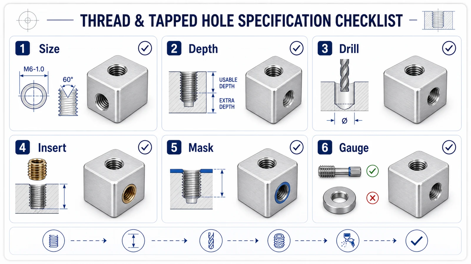
Send STEP and PDF drawings with thread callouts, depths, insert standards, finish condition, and quantity. If the part will be assembled often, mention that in the RFQ. If torque, load, pressure, or sealing matters, include enough context for engineering review.
Threads are easy to machine when they are specified clearly. They become expensive when the drawing leaves depth, finish, or insert requirements open.