
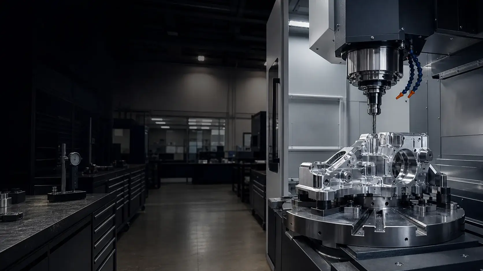
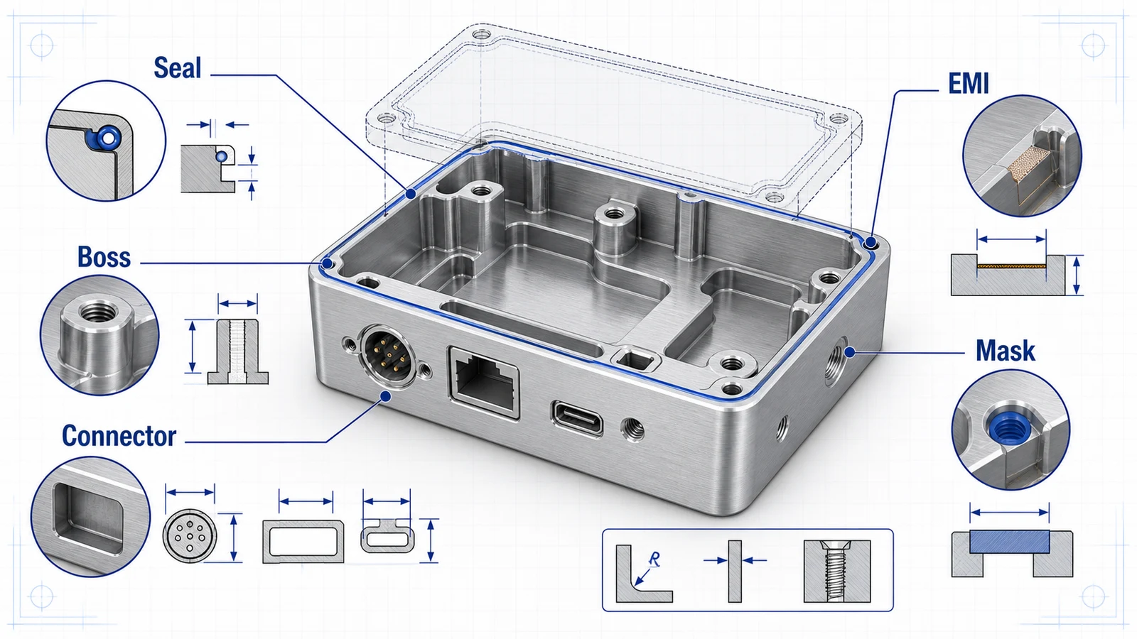
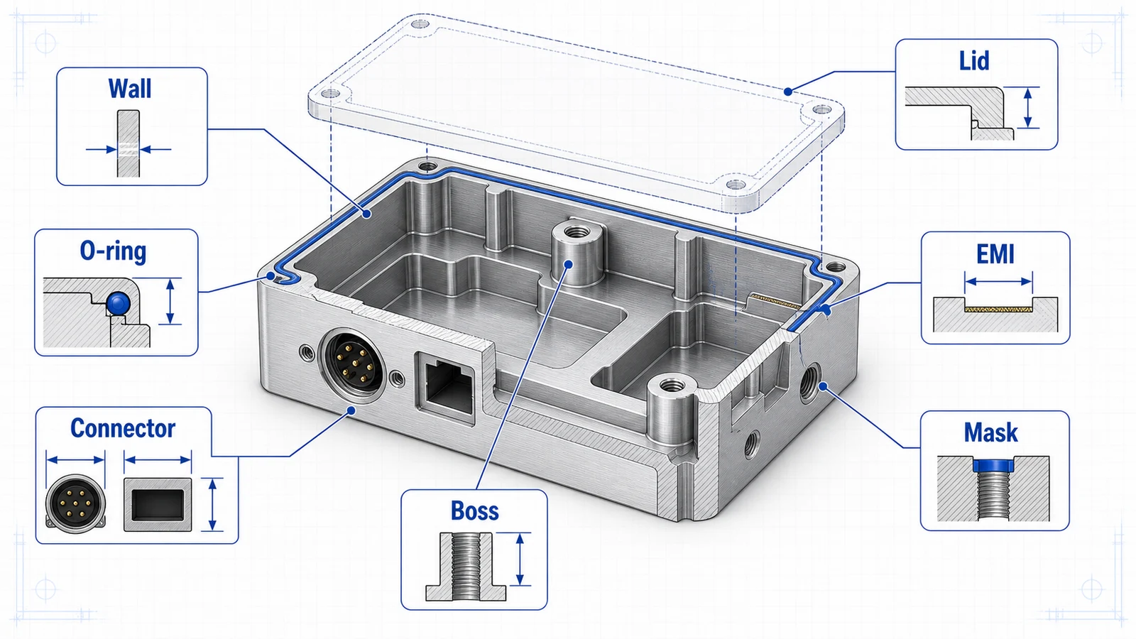
CNC machined aluminum housings look simple from the outside, but they combine many manufacturing risks: thin walls, deep pockets, threaded bosses, lid interfaces, connector cutouts, O-ring grooves, cosmetic anodizing, EMI contact areas, and tight relationships between faces. A good housing design makes those requirements explicit before the RFQ.
Most aluminum housings are machined from 6061-T6 because it balances strength, machinability, corrosion resistance, and anodize appearance. 7075 may be used for high-load structures. MIC-6 may be reviewed for flat plates or fixture-like covers, but it is not usually the default for structural enclosures.
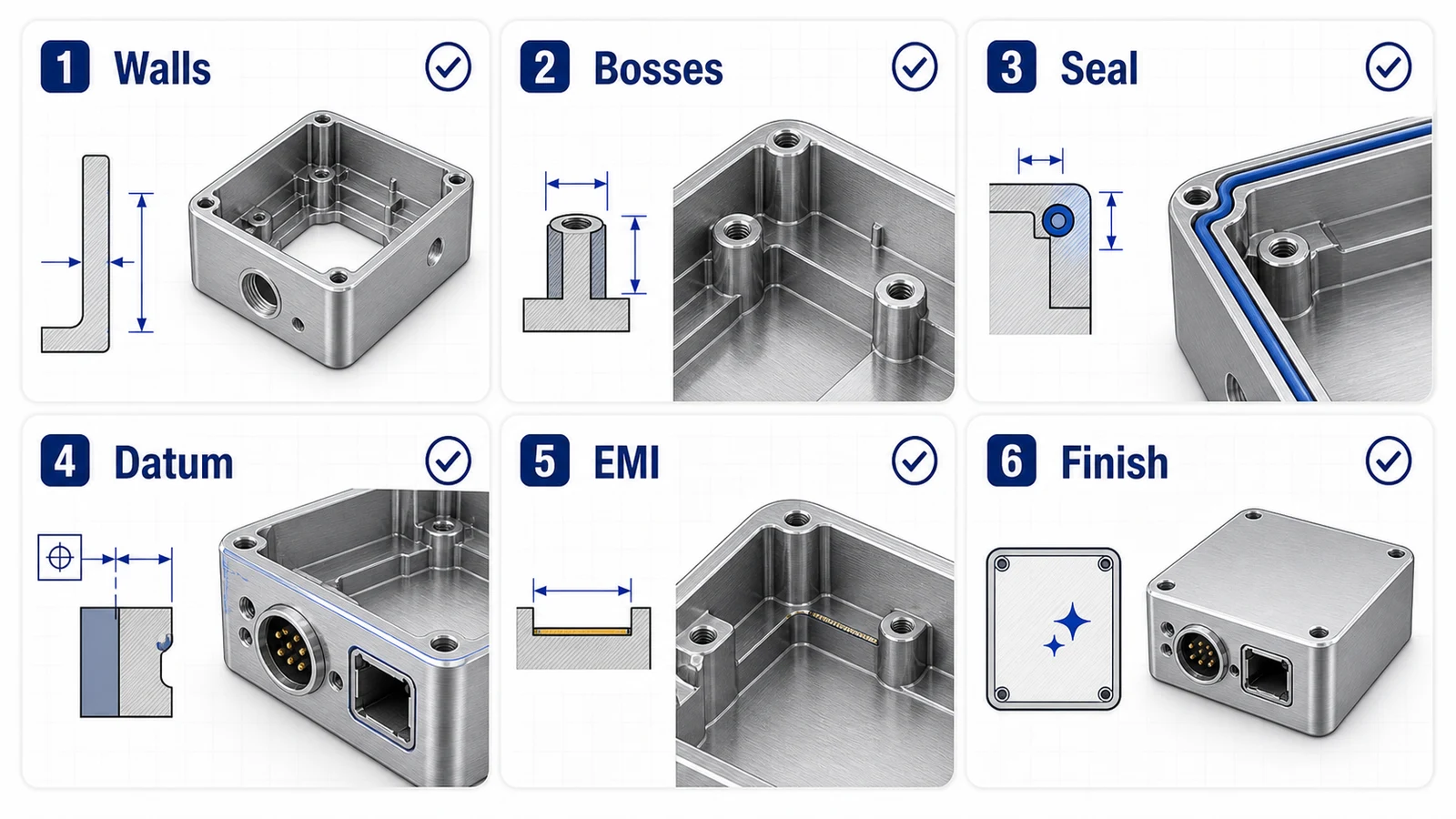
Housing design checklist
| Feature | Design guidance |
|---|---|
| Wall thickness | Use 1.5 mm or more where possible; review taller thin walls |
| Internal corners | Add radii that match practical end mills |
| Bosses | Support threaded bosses with ribs or generous base radii |
| Lid interface | Define flatness, gasket compression, and screw pattern |
| Connector faces | Use datums and position tolerances for functional cutouts |
| EMI lands | Mask anodize if conductivity is required |
| Finish | Define visible faces, bead blast, anodize color, and rack mark zones |
This checklist should be part of the first design review, not a final cleanup step.
Wall thickness and pockets
Deep pocketing removes a lot of material and can leave the housing flexible. Thin walls may chatter during finishing and move after unclamping. Keep walls consistent and add ribs where stiffness is needed. Avoid sharp internal corners and narrow deep slots that require long small tools.
If the housing must be very light, consider whether all weight reduction pockets are necessary. Sometimes a slightly thicker wall with fewer difficult pockets costs less and performs better than an aggressively lightened body.
For detailed wall guidance, use the thin wall aluminum machining guide.
Bosses, threads, and inserts
Threaded bosses are common in aluminum housings. They hold lids, PCBs, sensors, connectors, brackets, and covers. The boss should have enough diameter and base support to survive tapping, assembly torque, and repeated use.
For high-cycle screws or field-serviceable covers, threaded inserts may be better than tapped aluminum. Specify insert type, installation depth, and whether inserts are installed before or after anodize. If threads are anodized, check fit risk. If they are masked or tapped after finish, state it on the drawing.
Sealing surfaces and O-ring grooves
If the housing needs environmental sealing, the lid interface becomes a functional surface. Define groove width, groove depth, corner radii, surface finish, and flatness. Do not rely on general tolerances for an O-ring groove.
Screw spacing matters. Widely spaced screws may not compress the gasket evenly. Thin flanges may bow. If the enclosure needs IP-rated sealing, share the target with the supplier and consider a formal sealing review.
Connector and datum strategy
Connector cutouts, sensor bores, and mounting faces should be tied to datums. A connector opening dimensioned from a non-functional outside edge may be difficult to control in assembly. Choose datums that reflect how the housing locates in the product.
For multi-face housings, 5-axis machining may reduce setups and protect relationships between angled or adjacent features. For simpler boxes, 3-axis machining with planned setups may be more cost-effective.
Anodizing and EMI
Clear and black anodize are common for housings. Black anodize is often used for optics and customer-facing electronics. Clear anodize is common for industrial equipment. Hardcoat may be used where wear is important.
Anodize is insulating. EMI gasket lands, grounding pads, and threaded electrical contact points may need to remain conductive. Show masked areas clearly. Also define visible cosmetic faces and acceptable rack mark locations. The anodized aluminum CNC machining page covers these finish decisions in more depth.
RFQ package for housings
Send the STEP model, PDF drawing, alloy, finish, quantity, target lead time, critical dimensions, sealing notes, insert requirements, and cosmetic expectations. Include the mating lid, PCB, connector, or gasket details if they affect fit.
A housing is a system part. The more clearly the drawing communicates sealing, assembly, grounding, and appearance, the fewer surprises appear after machining.
For production housings, also separate prototype risk from release risk. A first article can prove the pocket strategy, lid fit, connector alignment, and anodize result before committing to a larger batch. If the enclosure will repeat, tell the supplier the expected annual volume so workholding, insert installation, and inspection can be planned for repeatability rather than one-off machining only.