
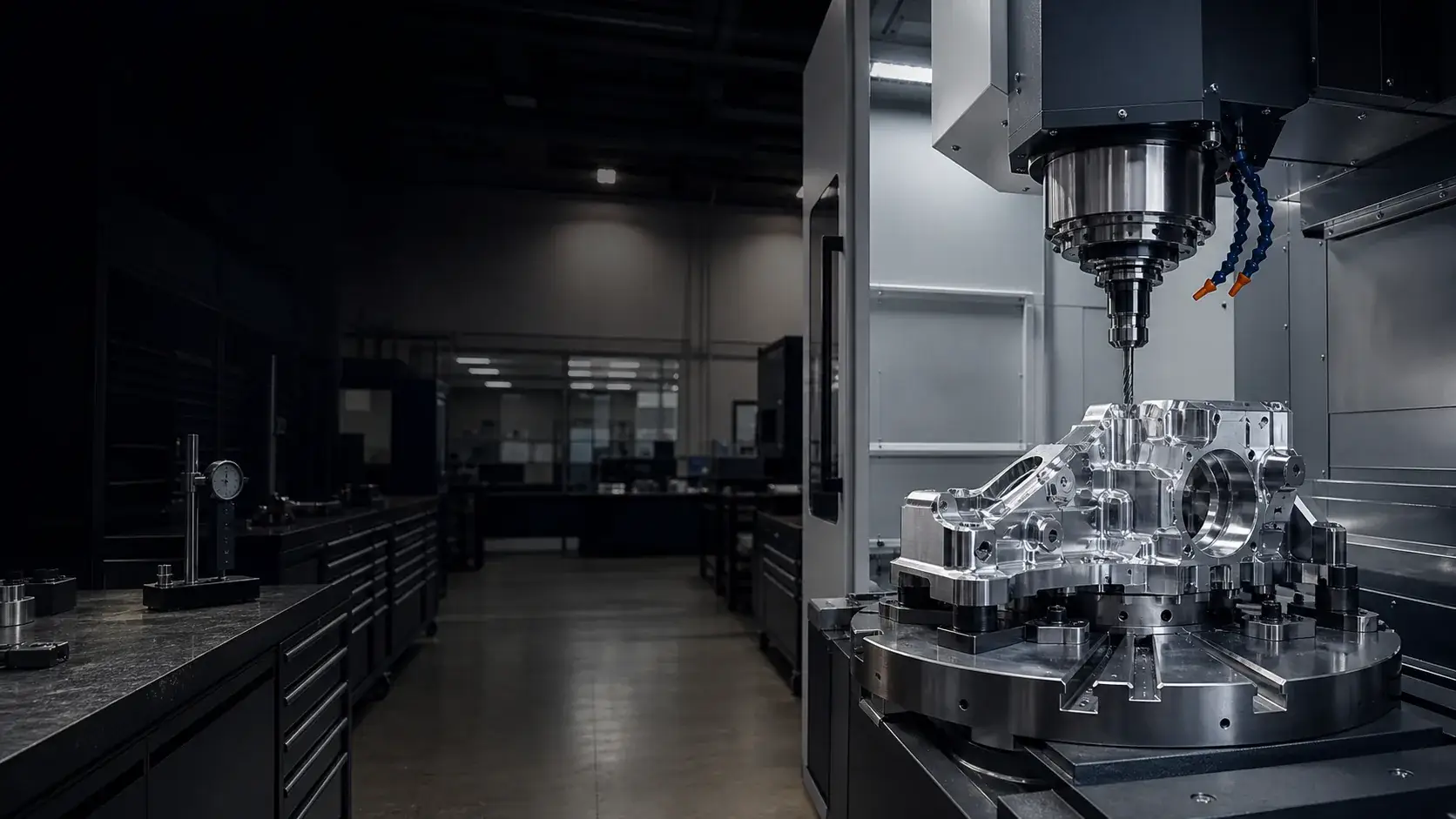
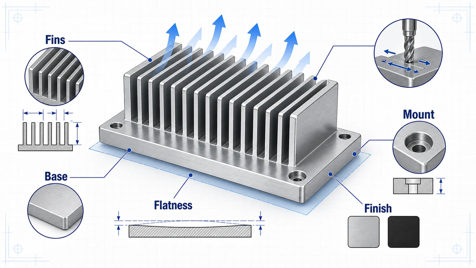
CNC machined aluminum heat sinks are used when an extruded heat sink cannot meet the geometry, mounting, sealing, or integration requirements of the product. They may combine fins, mounting holes, thermal interface surfaces, pockets, connector features, fluid passages, or housing details in one machined component.
The machining challenge is balancing thermal performance with manufacturability. Very thin fins, narrow spacing, tight base flatness, and cosmetic anodizing can all add cost if they are not designed around real cutter access and inspection requirements.
When CNC machining is the right heat sink process
Extrusions are cost-effective for long constant cross-sections. Die casting can work for high-volume complex shapes. CNC machining is best when the heat sink is custom, low-to-medium volume, integrated with other features, or needs precision mounting and flatness.
Examples include:
- Heat sinks integrated into electronics housings.
- Cold plate-like aluminum blocks with mounting features.
- Prototype thermal components before extrusion tooling.
- Heat sinks with non-standard fin patterns.
- Thermal mounting plates with tight hole location.
- Optics or laser module heat spreaders.
If the design is just a simple straight fin profile at high volume, extrusion may be better. If the heat sink also locates sensors, seals a housing, or interfaces with precision hardware, CNC machining may be the right choice.
Alloy selection
6061-T6 is common for CNC machined heat sinks because it machines well, is widely available, and provides reasonable thermal conductivity for many applications. 6063 is common in extrusions but less common for billet machining. 7075 is stronger but typically not selected for heat sinks unless structure dominates thermal needs.
If thermal conductivity is critical, share the heat load, interface size, airflow, and mounting condition. The supplier can machine the geometry, but thermal performance depends on the whole assembly.
Fin design for machinability
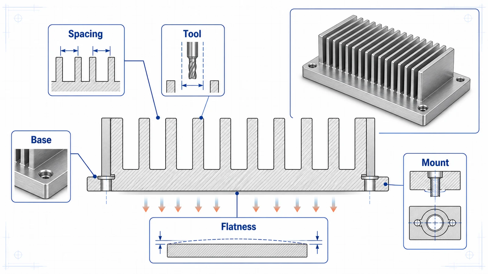
| Feature | Practical CNC guidance |
|---|---|
| Fin thickness | Avoid extremely thin tall fins unless performance justifies cost |
| Fin spacing | Leave enough space for cutter access and chip evacuation |
| Fin height | Tall fins need stiffness and may vibrate during machining |
| Corner radii | Accept tool radii at fin roots |
| Deburring | Plan for accessible edges and safe handling |
| Quantity | High volume may justify a different manufacturing process |
Thin fins increase surface area, but they also increase machining risk. The best design is not always the densest fin pack. Airflow, pressure drop, and manufacturability all matter.
Base flatness and thermal interface
The base surface that contacts a chip, module, thermal pad, or cold plate is often the most important feature. Specify flatness and surface roughness on that face only as tightly as needed. A tighter flatness callout may require stress control, light finishing passes, and careful inspection.
If thermal interface material will fill gaps, the flatness requirement may be less aggressive. If the part contacts a bare module or precision heat spreader, flatness and roughness become more important.
For large heat sinks, define whether flatness is inspected free state or under mounting condition. A thin base may flatten when bolted, but only if the mating surface and screw pattern support it.
Surface finish and anodizing
Black anodize is common for heat sinks because it can improve emissivity and provides corrosion protection. In forced convection systems, geometry and airflow often matter more than color. Clear anodize or as-machined surfaces may be acceptable depending on environment and appearance.
Anodize adds thickness. If the thermal interface face must stay bare for conductivity or flatness, specify masking. If electrical isolation is desired, anodize may be useful, but do not assume it replaces a designed insulator.
Mounting holes and threads
Heat sinks often include tapped holes, counterbores, PEM-style hardware, or inserts. Threads near thin fins can be difficult to machine and inspect. Keep threaded bosses supported and avoid placing small blind holes at the bottom of deep narrow fin gaps.
If a screw applies pressure to a thermal interface, define the mounting pattern and torque context. Uneven screw spacing can warp the base or reduce thermal contact.
RFQ package
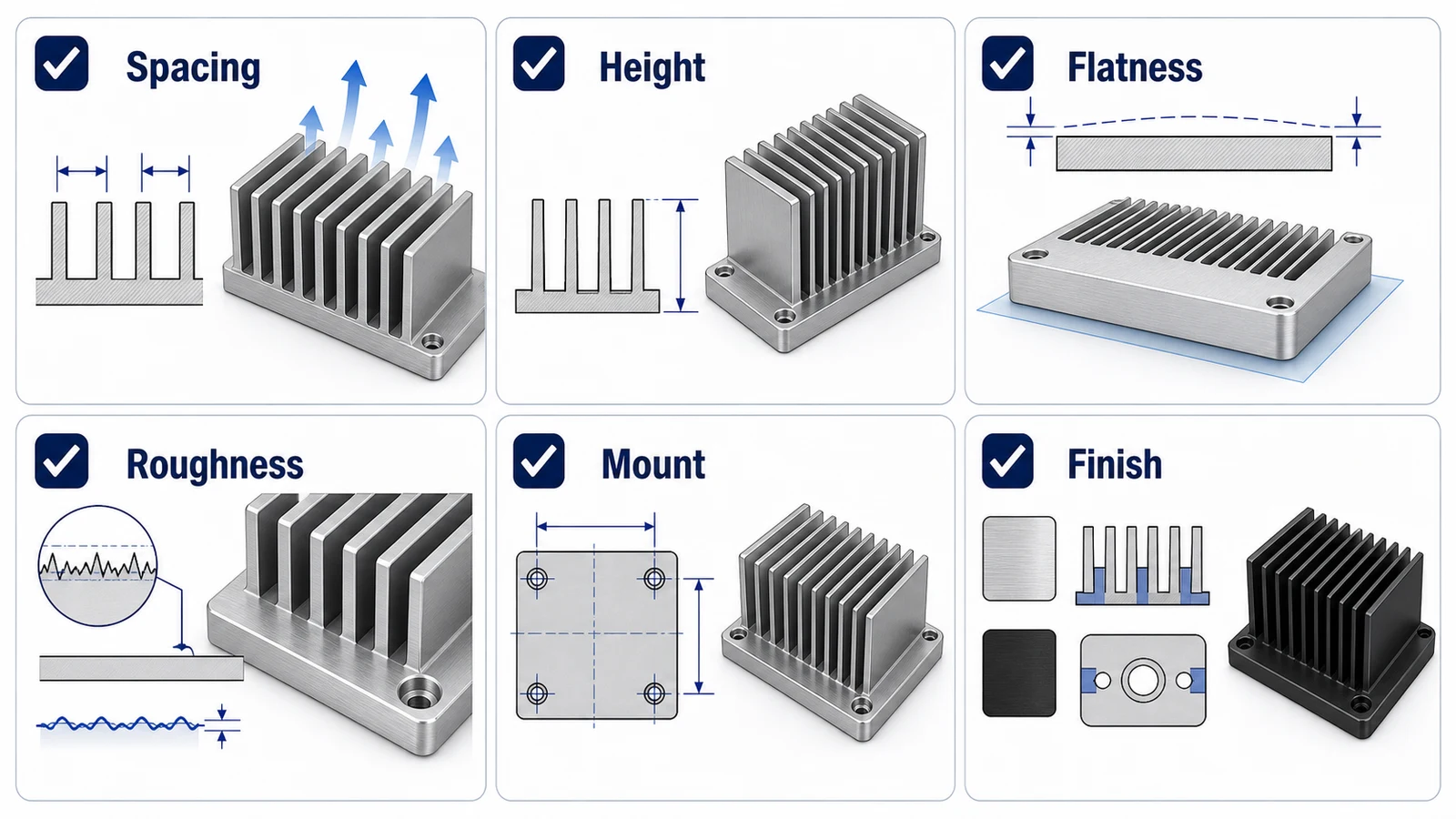
Send STEP, PDF drawing, alloy, finish, quantity, thermal interface requirements, critical flatness, surface roughness, mounting hole details, and whether any faces should be masked before anodizing. If you have a thermal model, include the assumptions that affect geometry, not necessarily the confidential analysis.
A CNC machined aluminum heat sink is both a thermal component and a machined part. Design the fins for airflow and cutter access, and design the base for real contact.