
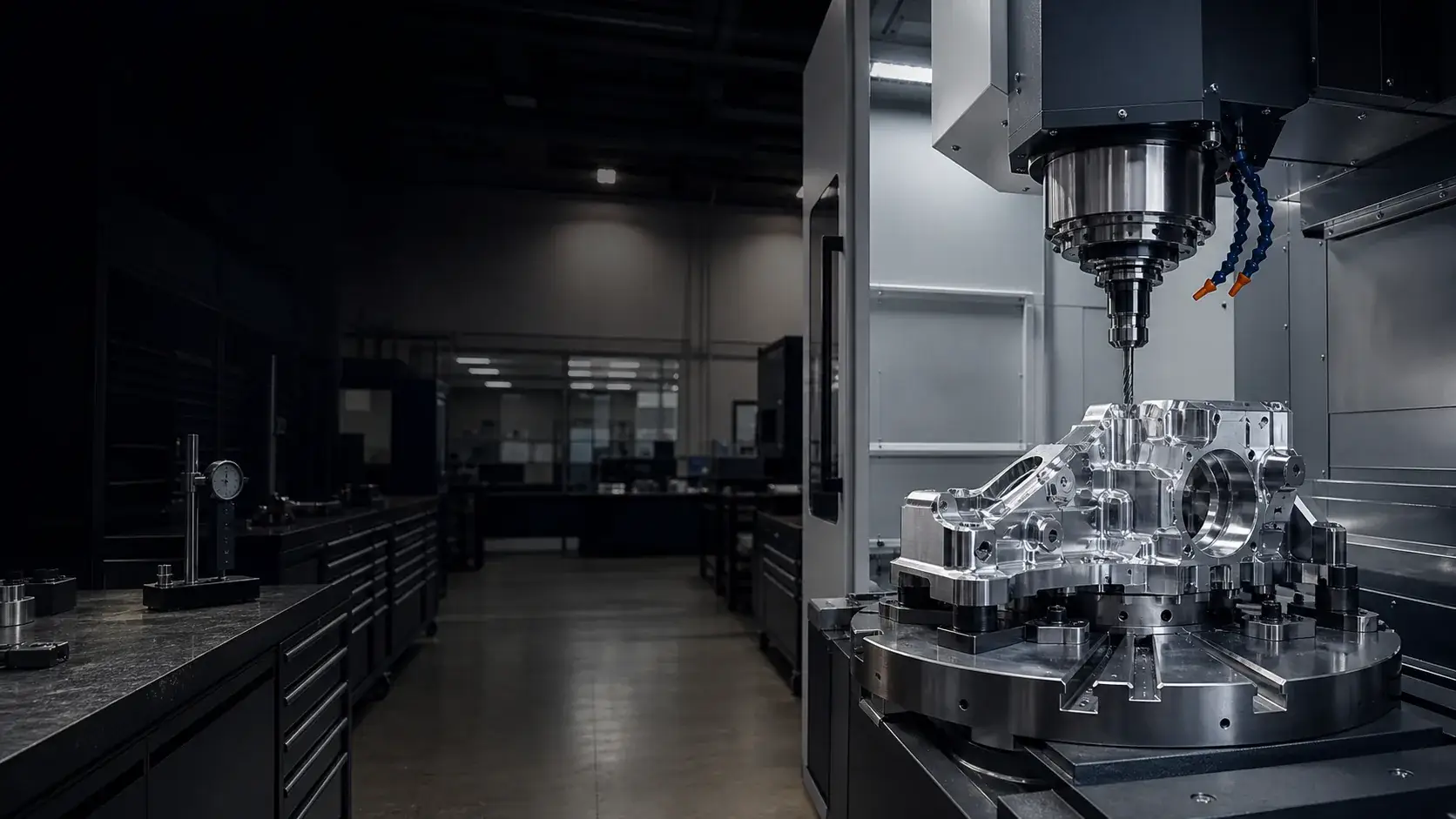
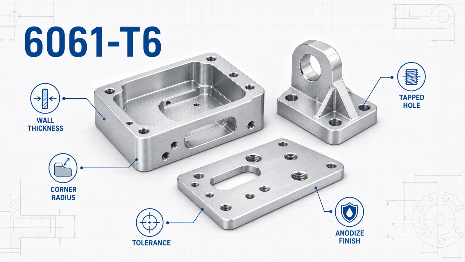
6061-T6 is the workhorse alloy for CNC machined aluminum parts. It is strong enough for many structural components, stable enough for accurate machining, available in many stock forms, and friendly to clear or black anodize. That combination is why engineers often specify 6061 for brackets, housings, plates, instrument panels, fixtures, manifolds, and general machine components.
The mistake is treating 6061 as automatic. A good 6061 design still needs realistic wall thickness, corner radii, thread engagement, tolerance strategy, and finish notes. The alloy is forgiving, but the part still has to survive stock removal, workholding, deburring, inspection, and shipping.
Start with the function of the 6061 part
Before adding dimensions, decide what the part must control. A 6061 enclosure may need connector alignment and a sealed lid. A bracket may need hole position and flat mounting faces. A fixture plate may need dowel bores and surface flatness. A cosmetic cover may care more about visible tool marks and anodize consistency than tight internal pocket dimensions.
That function should drive the drawing. Keep tight tolerances on the features that locate, seal, align, or carry load. Leave non-functional edges and clearance pockets with standard machining tolerances. This keeps the quote focused on real engineering value instead of treating every surface as critical.
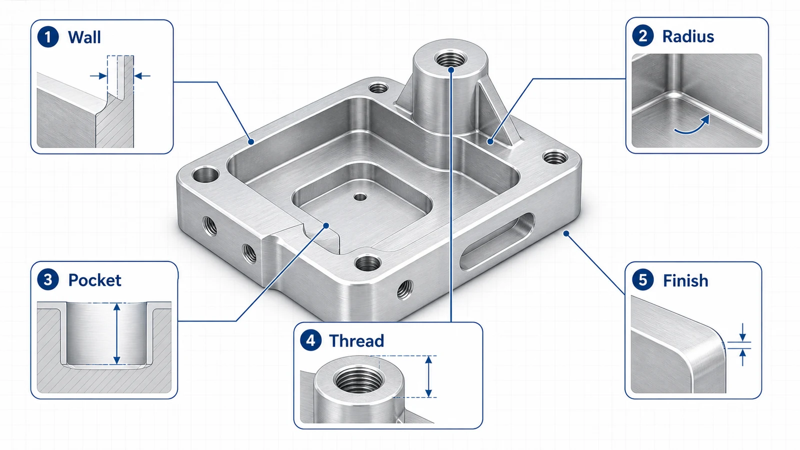
Practical 6061 design rules
| Feature | Practical guidance for 6061 CNC machining |
|---|---|
| Minimum wall thickness | 1.5 mm or more for standard production; thinner walls need review |
| Internal corner radius | Use the largest radius allowed; avoid sharp internal corners |
| Deep pockets | Keep depth under about 4 times tool diameter when possible |
| Threads | Use enough engagement, avoid thread depth at the bottom of blind holes |
| Flatness | Call out only functional faces and define inspection condition |
| Anodizing | State type, color, thickness, and whether dimensions apply after finish |
These are not absolute limits. They are practical starting points for reliable quotes.
Wall thickness and pocket design
6061 cuts cleanly, but thin walls can still vibrate or move after unclamping. For standard CNC milling, walls at 1.5 mm or thicker are usually manageable on moderate-height features. Short local walls can be thinner, especially on small parts, but tall thin ribs need support, lighter finishing passes, and a supplier review.
Avoid designing a pocket with full-depth, sharp internal corners. CNC end mills are round, so internal corners need radius. A corner radius that is slightly larger than the cutter radius gives the tool room to finish the wall instead of rubbing in the corner. This improves surface finish and reduces cycle time.
For housings and enclosures, keep wall thickness as even as possible. A part with one heavy wall and one thin wall may release stress unevenly after roughing. See the aluminum CNC housings and enclosures guide if your part combines deep pockets, sealing grooves, and cosmetic anodizing.
Tolerances that make sense for 6061
6061 can hold precise tolerances, but not every dimension deserves a tight tolerance. A general tolerance such as +/-0.10 mm may be reasonable for many machined features. Tighter dimensions, such as bearing bores, dowel holes, precision slots, or sealing land relationships, should be called out individually with datums.
If the part will be anodized, decide whether dimensions apply before or after anodize. For functional fits, post-anodize dimensions are usually what matter. A hole that is correct before coating may become tight after film growth. This is especially important for dowel bores, sliding fits, threaded inserts, and connector pockets.
Use geometric tolerancing when relationships matter. A hole position tolerance tied to datums is clearer than several independent plus/minus dimensions.
Threads, inserts, and fastening
6061 taps well and is commonly used for threaded aluminum parts. For low-cycle fastening, tapped aluminum threads may be enough. For repeated assembly, field service, or high clamp load, consider helical inserts or key-locking inserts. This is common in production housings, robotics brackets, and machine fixtures.
A good drawing should specify thread size, thread depth, whether the hole is blind or through, and any insert standard. If the part will be anodized, decide whether threads are masked, tapped after finish, or allowed to receive anodize. Anodize in small threads can change fit and create assembly problems.
Surface finish and anodizing
6061 is one of the best alloys for clear and black Type II anodize. It also works well with bead blasting before anodize for a uniform cosmetic surface. If the part is purely functional, an as-machined finish may be enough. If it will be handled, exposed to humidity, or sold as customer-facing hardware, anodizing usually adds practical value.
Specify finish in manufacturing terms, not vague appearance terms. “Clear anodize Type II, 10-15 microns, dimensions after finish” is much better than “silver finish.” For black parts, note whether the surface should be bead blasted before anodize, and identify masked electrical contact areas if conductivity matters.
RFQ package for 6061 parts
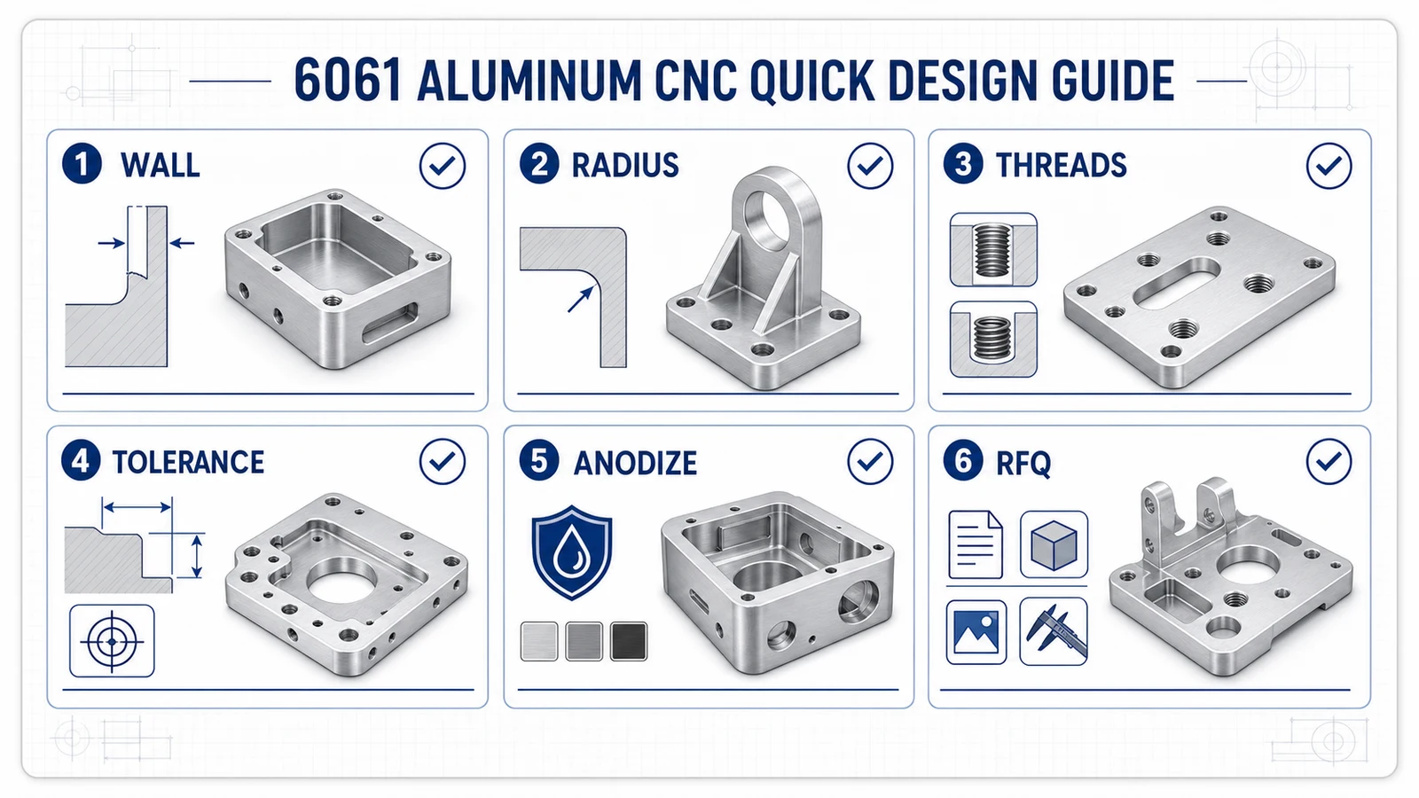
Send a STEP model for geometry and a PDF drawing for intent. The PDF should include alloy and temper, finish, quantity, critical tolerances, inspection requirements, and any cosmetic notes. If the part has multiple revisions, make the revision clear in both file names and title blocks.
When the supplier sees the function, not just the shape, they can recommend changes that reduce cost without weakening the part. That may include opening an internal radius, changing a blind tapped hole to a through hole, adjusting wall thickness, or moving a cosmetic surface away from a workholding mark.