
Air has to route through the block via deep drilled passages that intersect. Peck drilling and controlled break-through kept the bores straight and the intersections clean.
Case study · Manifold blocks
CNC Aluminum Manifold Block — Pneumatic Control Manifold
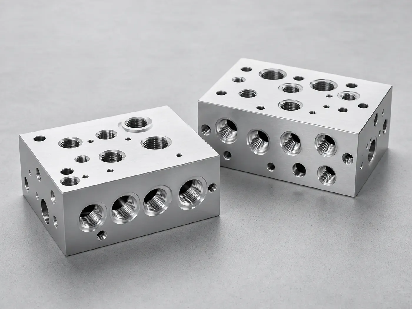
A 6061-T6 pneumatic manifold with cross-drilled internal passages, standard ports, and flat valve-mounting faces, leak-tested and chem-film finished for machine air control.
- 6061-T6
- Cross-drilled
- Leak tested
Project overview
Project overview
This project is a 6061-T6 pneumatic manifold block: a solid billet with valves and fittings on the outside and a network of cross-drilled passages routing air on the inside. Consolidating that routing into one machined block replaces a tangle of tubing with sealed passages that are more compact and easier to service.
The difficulty in a manifold is all internal. Passages are deep and they intersect, so the bores were peck-drilled with controlled break-through to stay straight, and every cross-hole intersection was deburred internally — not just at the surface — so burrs don’t restrict flow or shed into the system. The valve-mount faces were finished flat to 0.05 mm so gaskets and O-rings seat evenly and actually seal.
Before finishing, the block was pressure-tested with the passages plugged to confirm there are no cross-leaks or porosity. Chem film was chosen as the finish because it protects the aluminum and keeps it conductive without adding thickness inside the threads and passages. Block size, port standards, and test pressures are placeholders — the passage strategy, internal deburring, and leak testing are representative of the manifolds we machine.
Technical specification
Part specification
Key manufacturing parameters for this project. Values marked as placeholders stand in for confidential production data.
| Parameter | Specification |
|---|---|
| Block size | Placeholder — e.g. 150 × 60 × 40 mm |
| Port threads | Standard G / NPT ports per drawing |
| Passage diameter | Placeholder — deep cross-drilled bores |
| Valve-mount face flatness | 0.05 mm over the sealing footprint |
| Cross-hole intersections | Deburred internally for clean flow |
| General tolerance | ±0.05 mm (ISO 2768-f unless noted) |
Engineering challenges
What made this part difficult
The manufacturability risks we planned around before cutting metal.
Cross-hole intersections leave burrs that restrict flow and shed into the system. Intersections were deburred internally rather than only at the surface.
Valves and fittings only seal against a flat face. The valve-mount footprints were finished flat to 0.05 mm so gaskets and O-rings seat evenly.
Manufacturing process
How the part was made
The routing from raw stock to finished, inspected components.
- Step 1: Engineering review
Reviewed passage routing, port standards, and wall thickness between bores before quoting. - Step 2: Face and profile machining
Block squared up and valve-mount faces roughed from 6061-T6 billet. - Step 3: Deep-hole drilling
Passages peck-drilled with controlled break-through to keep bores straight. - Step 4: Porting and tapping
Ports drilled and tapped to the specified thread standard. - Step 5: Internal deburring
Cross-hole intersections deburred internally, then the block flushed clean. - Step 6: Leak test and finishing
Pressure / leak test, then chem film and final inspection.
Inspection methods
How quality was verified
Dimensional and process controls used to sign off the part. See our full aluminum part inspection process.
Passages plugged and pressurized to confirm no cross-leaks or porosity. Placeholder for the specified test pressure and hold time.
Valve-mount face flatness verified before finishing.
Full FAI including port positions and thread gauging; report available. Placeholder for AQL.
Surface finishing
Finishing and post-processing
Finishing decided alongside the machining plan. Compare options in the aluminum surface finishes hub.
Corrosion protection that keeps the block electrically conductive and does not add measurable thickness inside the passages or threads.
Port threads and sealing faces protected during finishing so fits and seals are unchanged.
Passages flushed and ports capped to keep debris out in transit.
Typical application
Where this manifold is used
Pneumatic manifolds consolidate valves, fittings, and air routing into a single machined block, replacing a nest of tubing with sealed internal passages that are easier to service and more compact.
Chem film is the natural finish here because it protects the aluminum without adding thickness inside threads and passages, and keeps the block conductive for grounding.
- Manufacturability review
Every project starts with an engineering review of tolerances, wall thickness, and finish before we quote. - Prototype to production
The same routing scales from a first article to recurring production batches. - Documentation
Material certificates and first article inspection reports are available on request.
Explore the engineering
Related capabilities, materials, and pages
This project connects to our wider aluminum machining program. Start with our engineering capabilities, then dive into the specific products, materials, industries, and finishes involved.
Case studies
More aluminum CNC machining case studies
Projects with comparable materials, tolerances, or finishing requirements.
Aluminum Housings Aluminum Control Module Enclosure — Sealed 6061 Housing
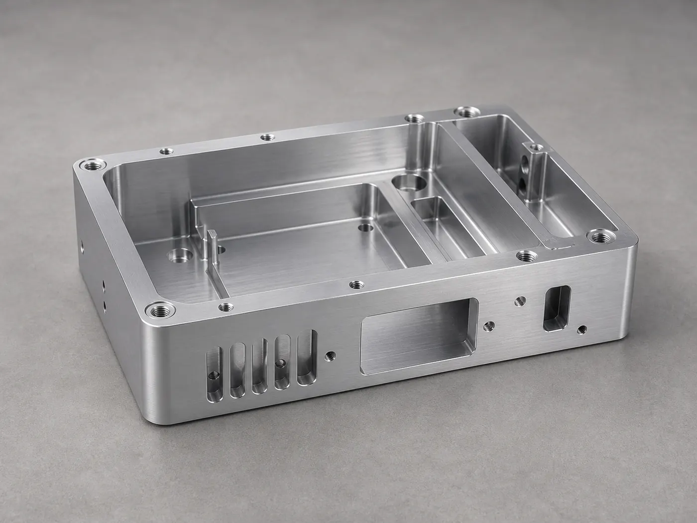
A sealed 6061-T6 control module enclosure with a machined O-ring gland, threaded service bosses, and a bead-blasted black anodize finish for vibration- and coolant-exposed environments.
Industrial Equipment Industrial Pump Housing — Machined 6061 Body with Sealed Bores
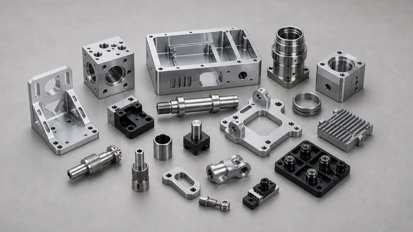
A 6061-T6 pump housing with concentric bearing bores and sealed internal passages, hardcoat and chem-film finished to survive vibration, wear, and coolant in industrial service.
Electronics Aluminum Electronics Housing — 6061-T6 Instrument Enclosure
A pocketed 6061-T6 instrument enclosure with connector cutouts, standoff bosses, and conductive grounding pads, machined and finished for a low-volume electronics build.
Browse the full engineering portfolio in the aluminum CNC machining case studies hub.
Have a similar part? Get it quoted by an engineer
Upload your CAD model and drawing with alloy, finish, and tolerance notes. We review manufacturability before quoting — not after the parts are on the machine.
- Engineering review within one business day
- Prototype to production
- Material certificates available
- ISO 9001 quality management