
The jig exists to transfer a hole pattern accurately, part after part. Bushing bores were held to ±0.02 mm true position off hard tooling datums so every drilled hole lands in the same place.
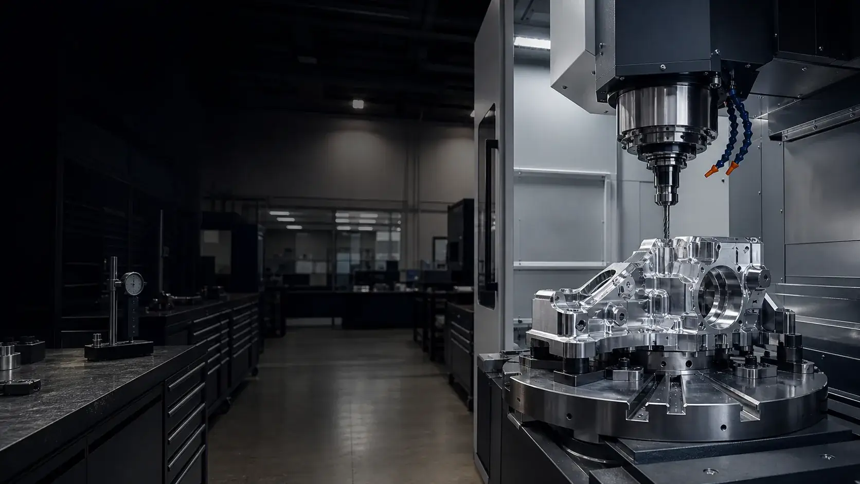
Case study · Aerospace tooling
Aerospace Drill Jig Fixture — Precision Hole-Pattern Tooling
An aluminum drill jig with hardened bushings and tight positional tolerances, hardcoat anodized and documented for repeatable aerospace hole patterns on the assembly line.
- Drill bushings
- ±0.02 mm position
- Documented FAI
Project overview
Project overview
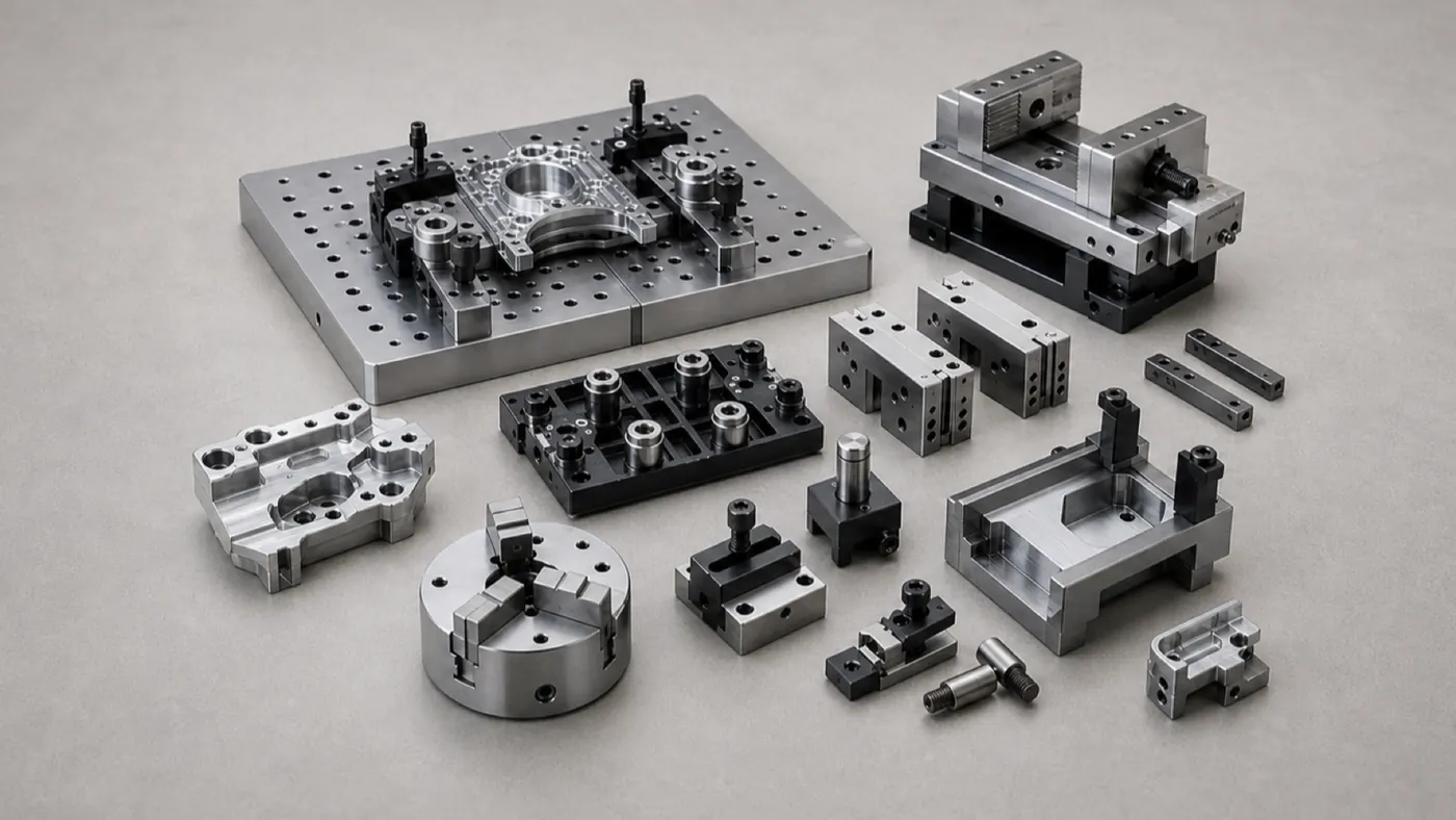
This project is an aluminum drill jig — a fixture whose whole job is to transfer a precise hole pattern into an aerospace assembly, part after part, without a CNC machine at the point of use. Hole position drives fit and fastener integrity on the assembly, so the jig has to place every hole in exactly the same spot over its production life.
Two things make that possible. First, the bushing bores are held to ±0.02 mm true position off hard tooling datums, so the pattern is accurate and repeatable at setup. Second, hardened, replaceable drill bushings carry the drilling wear — drills chew through aluminum quickly, so the wear lives in a swappable insert instead of the jig body. The body itself is stress-relieved and hardcoat anodized so it holds its geometry through handling and use.
Every tool ships with a documented CMM inspection report tying the bushing positions back to the tooling datums. Material, fixture size, and program quantities are placeholders — the datum strategy, hardened bushings, and documented inspection are representative of the aerospace tooling we machine, with no confidential program details fabricated.
Technical specification
Part specification
Key manufacturing parameters for this project. Values marked as placeholders stand in for confidential production data.
| Parameter | Specification |
|---|---|
| Fixture size | Placeholder — sized to the assembly footprint |
| Bushing hole position | ±0.02 mm true position off tooling datums |
| Bushing bore fit | Press / slip fit per bushing spec |
| Datum scheme | Hard tooling datums for repeatable setup |
| Flatness | 0.05 mm across the locating face |
| General tolerance | ±0.05 mm (ISO 2768-f unless noted) |
Engineering challenges
What made this part difficult
The manufacturability risks we planned around before cutting metal.
Drills wear aluminum bores quickly, so hardened, replaceable drill bushings carry the wear and can be swapped without scrapping the jig.
A jig that moves is worse than no jig. The body was stress-relieved and hardcoat anodized so it holds its geometry through production use.
Manufacturing process
How the part was made
The routing from raw stock to finished, inspected components.
- Step 1: Engineering review
Confirmed datum scheme, bushing fits, and positional tolerances before quoting. - Step 2: Body machining
Fixture body machined from tooling-grade aluminum plate with a stress-relief step. - Step 3: Datum finishing
Hard tooling datums and locating face finished to establish the reference. - Step 4: Bushing bore machining
Bushing bores machined to fit and ±0.02 mm position off the datums. - Step 5: Masking and hardcoat
Bushing bores masked, then hardcoat anodize on the body wear surfaces. - Step 6: Bushing fit and documented inspection
Hardened bushings fitted, then full CMM inspection with a documented report.
Inspection methods
How quality was verified
Dimensional and process controls used to sign off the part. See our full aluminum part inspection process.
Bushing positions mapped on a CMM against the tooling datums, with a documented report supplied for the program.
Bushing bore fits confirmed before and after finishing.
Full FAI on the tool with documentation. Placeholder for the program's specific quality requirements.
Surface finishing
Finishing and post-processing
Finishing decided alongside the machining plan. Compare options in the aluminum surface finishes hub.
Wear-resistant surface on the jig body so handling and contact don't degrade the tool over its life.
Bushing bores masked so hardcoat growth does not disturb the press/slip fits.
Chem film available where conductivity or a thinner coating is preferred on specific features.
Typical application
Where this drill jig is used
Drill jigs let an assembly line transfer a precise hole pattern into structure repeatedly, without a CNC machine at the point of use — critical for aerospace assemblies where hole position drives fit and fastener integrity.
Aluminum with hardened bushings gives a light, handleable tool that still resists drill wear, and hardcoat anodize keeps the body stable through production.
- Manufacturability review
Every project starts with an engineering review of tolerances, wall thickness, and finish before we quote. - Prototype to production
The same routing scales from a first article to recurring production batches. - Documentation
Material certificates and first article inspection reports are available on request.
Explore the engineering
Related capabilities, materials, and pages
This project connects to our wider aluminum machining program. Start with our engineering capabilities, then dive into the specific products, materials, industries, and finishes involved.
Case studies
More aluminum CNC machining case studies
Projects with comparable materials, tolerances, or finishing requirements.
Fixtures & Tooling Precision Aluminum Fixture Plate — MIC-6 Inspection Base
A MIC-6 cast-plate fixture with an H7 dowel and tapped-hole grid on a flat datum face, machined to stay flat after pocketing for repeatable workholding and inspection.
Automation Equipment Automation Gripper Baseplate — Dowelled 6061 Tooling Plate
A 6061-T6 gripper baseplate with an H7 dowel grid, sensor pockets, and hardcoat anodize, built as a repeatable, wear-resistant mounting base for high-cycle end-of-arm tooling.
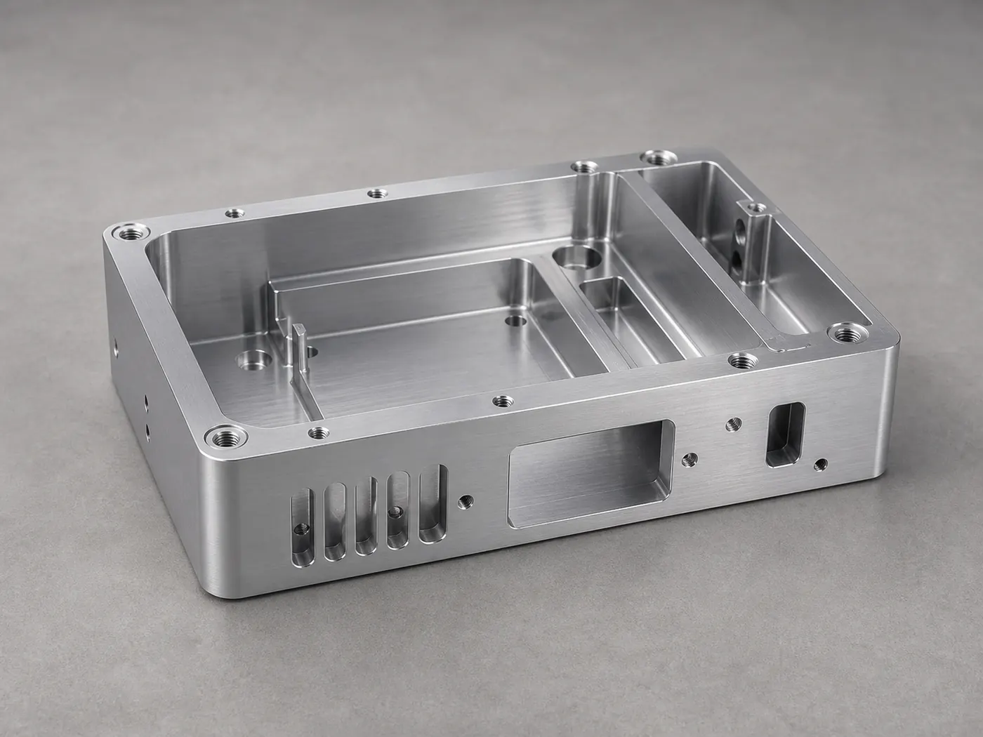
Electronics Aluminum Electronics Housing — 6061-T6 Instrument Enclosure
A pocketed 6061-T6 instrument enclosure with connector cutouts, standoff bosses, and conductive grounding pads, machined and finished for a low-volume electronics build.
Browse the full engineering portfolio in the aluminum CNC machining case studies hub.
Have a similar part? Get it quoted by an engineer
Upload your CAD model and drawing with alloy, finish, and tolerance notes. We review manufacturability before quoting — not after the parts are on the machine.
- Engineering review within one business day
- Prototype to production
- Material certificates available
- ISO 9001 quality management