
A motor pilot bore that is not concentric with the bolt circle preloads the bearings. Both were machined in one setup off a common datum to hold concentricity.
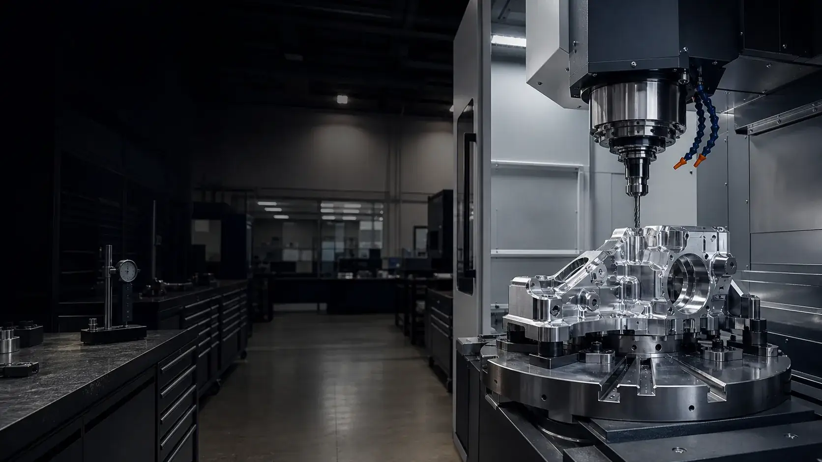
Case study · Brackets & mounts
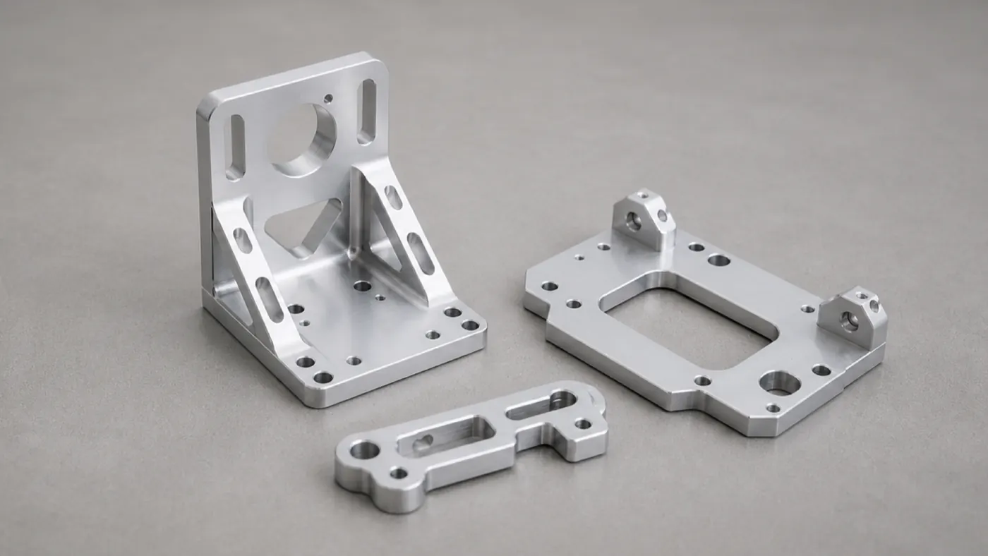
Aluminum Motor Mount Bracket — 6061 Precision Mounting Plate
A 6061-T6 motor mount bracket with a toleranced bolt circle, pilot bore, and dowel location, machined and clear anodized for repeatable drive alignment on automation equipment.
- 6061-T6
- Bolt circle
- Dowel location
Project overview
Project overview
This project is a 6061-T6 motor mount bracket — a plate that carries a drive motor and locates it precisely on a machine frame. It looks like a simple part, but everything it does depends on two relationships: the pilot bore has to be concentric with the bolt circle, and the whole bracket has to drop back into the same place after service.
Both requirements are met the same way — a common datum. The mounting face and datum edges are finished first to establish the reference, then the pilot bore, bolt circle, and dowel holes are all machined off that datum in a single setup. The dowel holes are reamed to an H7 fit so the bracket repeats its position rather than floating on clearance holes, and the mounting face is held flat to 0.05 mm so it doesn’t rock under bolt load.
Clear anodize protects the part and keeps the machined aluminum look, with the pilot and dowel holes masked so anodize growth doesn’t creep into the fits. Sizes and volumes are placeholders — the datum strategy and fit callouts are representative of the mounting brackets we machine.
Technical specification
Part specification
Key manufacturing parameters for this project. Values marked as placeholders stand in for confidential production data.
| Parameter | Specification |
|---|---|
| Overall size | Placeholder — e.g. 120 × 120 × 12 mm plate |
| Pilot bore | H7 fit to the motor pilot; concentric to bolt circle |
| Bolt circle position | ±0.02 mm true position |
| Dowel holes | H7 reamed for repeatable location |
| Flatness | 0.05 mm across the mounting face |
| General tolerance | ±0.05 mm (ISO 2768-f unless noted) |
Engineering challenges
What made this part difficult
The manufacturability risks we planned around before cutting metal.
The bracket has to drop back into the same position every time it is serviced, so dowel holes were reamed to H7 rather than relying on clearance holes.
A bracket that is not flat rocks and shifts alignment under bolt load. The mounting face was finished last and held to 0.05 mm flatness.
Manufacturing process
How the part was made
The routing from raw stock to finished, inspected components.
- Step 1: Engineering review
Confirmed pilot fit, bolt-circle tolerance, and datum scheme before quoting. - Step 2: Machining from plate
Profile, pockets, and clearance features cut from 6061-T6 plate. - Step 3: Datum finishing
Mounting face and datum edges finished to establish the reference for the accuracy features. - Step 4: Bore and bolt circle
Pilot bore, bolt circle, and dowel holes machined off the common datum in one setup. - Step 5: Deburr and clean
Edge-break and cleaning ahead of anodize. - Step 6: Anodize and inspection
Clear anodize, then CMM verification of position and fit.
Inspection methods
How quality was verified
Dimensional and process controls used to sign off the part. See our full aluminum part inspection process.
Bolt circle and dowel positions verified on a CMM against the datum scheme.
Pilot bore concentricity to the bolt circle confirmed before sign-off.
Full FAI on the first part with a report available; placeholder for the program's AQL.
Surface finishing
Finishing and post-processing
Finishing decided alongside the machining plan. Compare options in the aluminum surface finishes hub.
Corrosion protection and a clean industrial finish while keeping the machined aluminum tone.
Pilot bore and dowel holes masked so anodize growth does not change the fits.
Typical application
Where this bracket is used
Motor and gearbox mounts sit at the interface between a drive and a machine frame, where alignment errors turn straight into bearing wear, noise, and lost accuracy.
Machining the pilot, bolt circle, and dowels off one datum makes the bracket a precise, repeatable interface rather than a loose plate with holes.
- Manufacturability review
Every project starts with an engineering review of tolerances, wall thickness, and finish before we quote. - Prototype to production
The same routing scales from a first article to recurring production batches. - Documentation
Material certificates and first article inspection reports are available on request.
Explore the engineering
Related capabilities, materials, and pages
This project connects to our wider aluminum machining program. Start with our engineering capabilities, then dive into the specific products, materials, industries, and finishes involved.
Case studies
More aluminum CNC machining case studies
Projects with comparable materials, tolerances, or finishing requirements.
Robotics 7075 Robotic Arm Bracket — Lightweight Structural Link
A 7075-T6 structural arm bracket with lightweighting pockets, precise bearing bores, and hardcoat anodize, machined for stiffness-to-weight in a robotic joint.
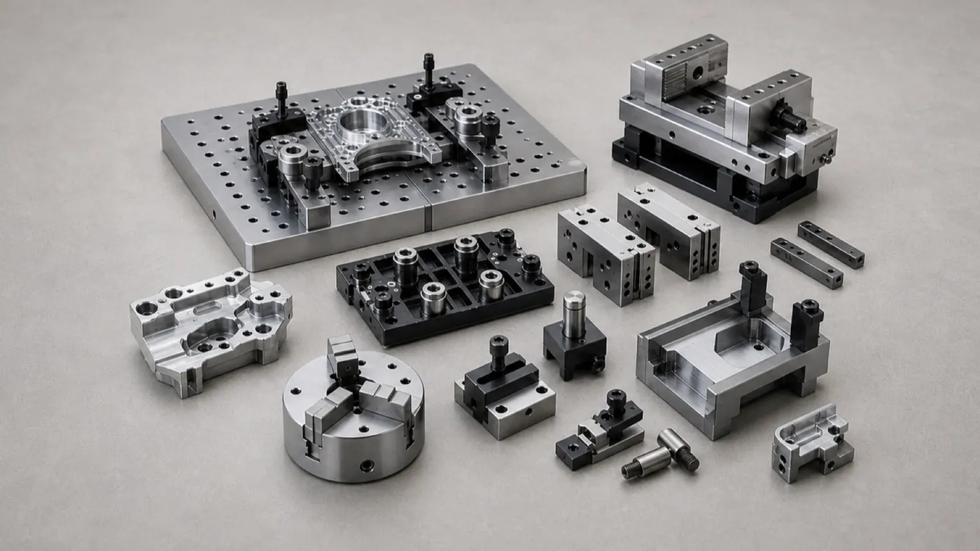
Automation Equipment Automation Gripper Baseplate — Dowelled 6061 Tooling Plate
A 6061-T6 gripper baseplate with an H7 dowel grid, sensor pockets, and hardcoat anodize, built as a repeatable, wear-resistant mounting base for high-cycle end-of-arm tooling.
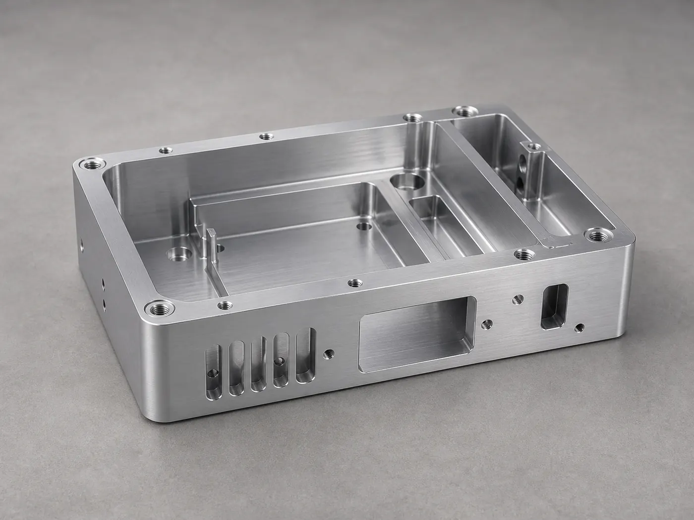
Electronics Aluminum Electronics Housing — 6061-T6 Instrument Enclosure
A pocketed 6061-T6 instrument enclosure with connector cutouts, standoff bosses, and conductive grounding pads, machined and finished for a low-volume electronics build.
Browse the full engineering portfolio in the aluminum CNC machining case studies hub.
Have a similar part? Get it quoted by an engineer
Upload your CAD model and drawing with alloy, finish, and tolerance notes. We review manufacturability before quoting — not after the parts are on the machine.
- Engineering review within one business day
- Prototype to production
- Material certificates available
- ISO 9001 quality management